The magnetization curve of the current transformer shows the relationship between the secondary excitation current and secondary excitation voltage. The equivalent circuit diagram of the current transformer is given below.
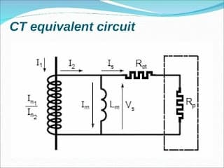
Schematic diagram of CT
I1: primary current.
I2: Kn I1: secondary current for a perfect CT.
Is: secondary current flowing through the circuit.
Im: magnetizing current.
E: induced electromotive force.
Vs: output voltage.
Lm: magnetization inductance (saturable) equivalent to the CT.
Rct: resistance at the CT secondary
Rp: load resistance.
How does CT Work?
The current transformer has two sets of winding around the magnetic core. When alternating current (Ip) flows in the primary, the alternating field (H=Np*Ip) is generated, and the magnetic flux flows in the core. The magnetic flux gets linked to the secondary of the CT and produces a voltage (Vs) in the secondary.
If the secondary of the current transformer is not connected to a burden, the secondary current will be zero. In the absence of the secondary current(Is), the core’s net magnetic flux will equal the flux created by the primary current. The higher flux density in the core will saturate the core, and the dangerously high voltage is produced across the secondary under this condition. That is why the secondary of the current transformer must not be kept open-circuited.
If the secondary of the current transformer is connected to a burden, the secondary current will set up its own magnetic flux in the core, and the flux generated due to the secondary current opposes the flux generated by the primary. Thus, the net flux density in the core is below the rated flux density of the core, and the secondary voltage is in order of the few volts.
In the current transformer, when connected to burdens like a protection relay, energy meter, or ampere meter, the total current that passes through the CT is magnetizing current (Im) & secondary current (Is).
Thus, the total secondary current is the vector sum of the magnetizing current (Im) and secondary load current (IL) flowing through the protection relay. The magnetizing current can go above its knee point voltage during fault conditions, and CT gets saturated.
Just below the knee point voltage, all the magnets are aligned in the same direction as the magnetic field, and the maximum rated flux density of the core has reached. If the primary current is further increased after attaining the maximum flux density in the core, the core can’t handle this increased magnetic field, and CT is said to be saturated.
Magnetization Curve of CT Zones
The magnetization curve of CT can be divided into three zones.
Three Zones of the CT curve are as follows.
- Non-saturated Zone
- Intermediate Zone
- Saturated Zone
The three operating zones are shown in the below CT curve.
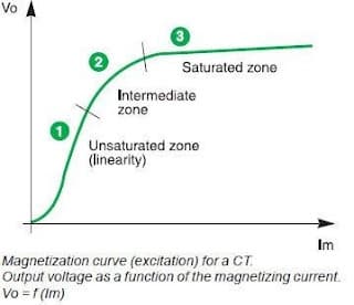
1. Non-saturated Zone
In the non-saturated zone of the magnetizing CT curve, the CT consumes a very low magnetizing current, and the secondary current is almost linear to the primary current. The ratio error is minimum in this zone, and the current transformer used for measuring the electrical parameters like ampere, power, and energy must be operated in this zone. The metering class CT operates in this region. The current transformer class for the metering CT is 0.1s, 0.2s, 0.5s & 1.0s.
2. Intermediate Zone
In the intermediate Zone, the magnetizing current increases with an increase in the primary current, and the secondary current is not proportional to the primary current. Non-linearity increases as the primary current increases.
The protection class current transformer is operated in this zone. During a fault, the magnitude of the primary current is in the order of kilo-amperes, and it is expected that CT will not get saturated when sensing the fault current, or else the protection system will not work.
3. Saturated Zone
The CT magnetization curve becomes virtually horizontal because of the drastic increase in magnetizing current, and the error in transformation ratio is high; the secondary current is distorted by saturation. No electrical network protection can be ensured if the current transformer is operated in this zone.
Related Articles:
Nice article
for sure