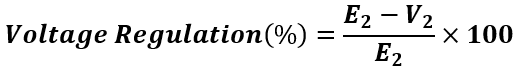
What is the Voltage Regulation of a Transformer?
Voltage regulation of the transformer is defined as the percentage change in the transformer’s secondary voltage from no load to full load. In other words, the transformer voltage regulation describes the ability of the transformer to provide a constant voltage from no load to full load. The secondary voltage of the transformer should not vary with load when the input supply is constant. The transformer can be treated as a voltage source, and the variation in the secondary terminal voltage from no load to full load depends on the voltage drop in the transformer winding.
When current flows through the transformer, the voltage drop takes place due to the reactance and resistance of the transformer. The variation in the secondary output voltage of the transformer from its no load to full load is called the voltage regulation of the transformer.
Transformer Voltage Regulation Formula
The voltage regulation of the transformer shows how well a transformer maintains constant secondary output voltage from no load to full load condition when the primary voltage is constant. The voltage regulation formula is given below.
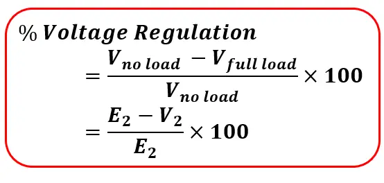
Where,
Vno load is the voltage at no load, and Vfull load is the voltage at full load.
Because of the voltage drop in the transformer winding, the secondary output voltage decreases as the current flowing through the transformer increases. The secondary output voltage at full load is always less than the output voltage at no load. The lesser the voltage difference between the no-load and full-load conditions, the better the transformer regulation. The lower voltage regulation means better regulation.
Example of Voltage Regulation :
The transformer’s secondary output voltage is 220 volts at no load. It decreases from 220 to 210 volts when the transformer is loaded to its full load current capacity.
The drop in the secondary output voltage from no load to full load = 10 Volts
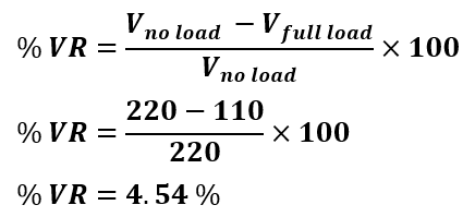
If the secondary voltage decreases from 220 to 215 volts when the transformer is loaded up to its full load current capacity. The regulation of the transformer, in this case, is 2.27 %. The % regulation of the transformer should be as minimum as possible to have almost constant secondary output voltage. Also, the copper loss decreases when the voltage regulation of the transformer improves.
What Factors Affect the Transformer Voltage Regulation?
The following factors affect the voltage regulation of the transformer.
- Resistance per phase: The resistance of the primary and secondary winding causes a voltage drop: the higher the resistance, the more the voltage drops. Transformer with higher primary and secondary resistance has poor voltage regulation.
- Reactance per phase: The reactance of the primary and secondary winding causes a voltage drop. The higher the reactance, the more the voltage drops. Transformer with higher primary and secondary reactance has poor voltage regulation.
- Leakage Flux: If leakage flux is higher, the leakage reactance XL increases, which increases the Ia XL voltage drop. Hence, regulation becomes poor.
- The magnitude of secondary load current: If load current increases, IaRa and IaXL voltage drop increases. Therefore, the terminal’s voltage drops, which makes regulation poor.
- Load Power factor: The load power factor also affects the transformer voltage regulation. The lagging power factor demands more current, and it causes more voltage drop in transformer winding. As a result, the voltage regulation of the transformer deteriorates. The leading power factor increases the transformer’s secondary voltage, and thus, the regulation of the transformer improves.
The transformer has primary and secondary winding. The winding has resistance and reactance. The primary resistance and reactance can be referred to as the secondary side or vice versa. The voltage regulation of the transformer depends on the reactance and the resistance of the transformer. The equivalent secondary circuit of the transformer is given below.
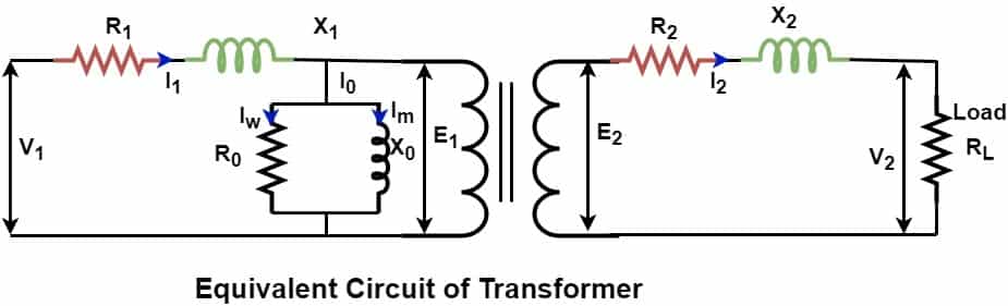
When the transformer is at no load, the secondary current I2 =0, and the transformer draws only a no-load current. The voltage drop I2Z2 across secondary impedance occurs with an increase in the secondary current. The voltage drop in the secondary winding is maximum when the transformer operates at its rated kVA capacity, delivering the rated secondary current to the load.
At no load, the secondary terminal voltage = E2
At rated secondary current, the voltage drop = I2Z2
At rated secondary current, the terminal voltage = V2
According to KCL,
E2 = I2Z2 + V2
E2 – V2 = I2Z2
The regulation of the transformer depends on the power factor of the load. Now, we will discuss the regulation of the transformer at lagging, leading, and unity power factor.
Voltage Regulation of Transformer for Lagging Power Factor
Let the angle between the secondary terminal voltage V2 and secondary current I2 be θ2. The phasor diagram of the no-load voltage(E2 ), full load voltage (V2), and current (I2)is shown below.
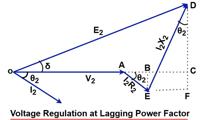
From the above diagram,
OC = OA + AB + BC
In triangle ABE
AB = AE Cosθ2
In triangle DEF,
DC = DE Sinθ2
The angle between OC and OD is very small, and OC is equal to OD.
OC = OD
OC = OA + AB + BC
E2 = V2 + AE Cosθ2 + DE Sinθ2
E2 = V2 + I2R2 Cosθ2 + I2X2 Sinθ2
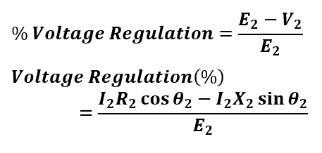
E2 – V2 = I2R2 Cosθ2 + I2X2 Sinθ2
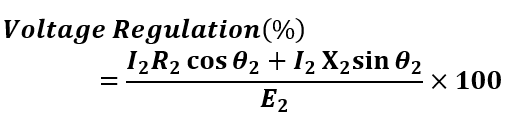
The transformer’s voltage regulation can be expressed as,
Putting the value of E2 and V2 in the above equation, we get,
Voltage Regulation of Transformer for Leading Power Factor
The phasor diagram of the transformer operating at the leading power factor is shown below.
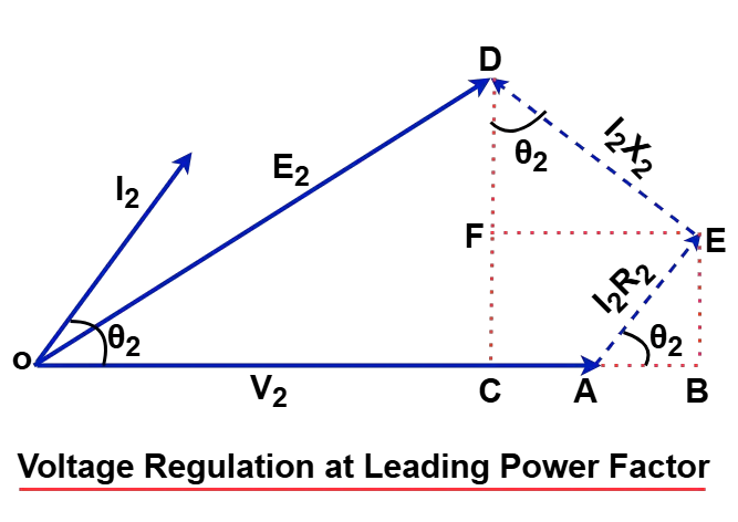
From the above diagram,
OC = OA + AB – BC
In triangle ABE,
AB = AE Cosθ2
In triangle DEF,
BC = DE Sinθ2
The angle between OC and OD is very small, and OC equals OD.
OC = OD
OC = OA + AB – BC
Here, OA = V2
E2 = V2 + AE Cosθ2 – DE Sinθ2
E2 = V2 + I2R2 Cosθ2 – I2X2 Sinθ2
E2 – V2 = I2R2 Cosθ2 – I2X2 Sinθ2
Putting the value of E2 and V2 in the equation below, we get voltage regulation at the leading power factor,
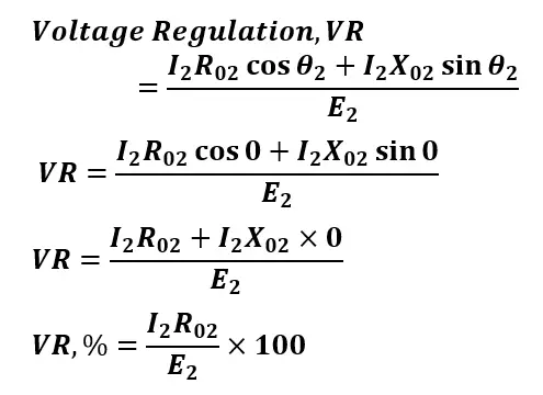
Voltage Regulation of Transformer for Unity Power Factor
The secondary current and voltage are in phase for a unity power factor. Since the transformer delivers only active power to the load, the current through the transformer is lower, resulting in better voltage regulation than lagging power factor loads. The formula for the voltage regulation for the unity power factor is,
Zero Voltage Regulation of Transformer
The secondary terminal voltage of the transformer at no load and the load can’t be equal if the transformer supplies power to resistive and inductive loads. The zero voltage regulation of the transformer is an ideal case, and practically it can not be zero for resistive and inductive loads. An ideal transformer has zero hypothetical voltage regulation. Therefore, zero voltage regulation is called ideal voltage regulation.
If the transformer is connected to the capacitive loads like a capacitor. In that case, the reactive power drawn by the load can compensate for the voltage drop in the transformer winding and you can achieve zero voltage regulation.
How to Improve the Transformer Regulation?
A high percentage of voltage regulation indicates a large voltage drop across the transformer windings. Lower voltage regulation is preferable as it enhances the transformer’s efficiency. Transformer voltage regulation can be improved by:
- Designing windings with larger cross-sectional areas reduces resistance, which minimizes I2R losses.
- Reduce leakage reactance by placing primary and secondary windings closer together.
- Ensure proper core design to minimize stray flux and leakage paths.
- Use low-loss high-grade silicon steel laminations with narrow hysteresis loops.
- Operate the transformer in parallel to reduce the current of the individual transformer.
- A tap changer in the transformer allows adjustment of the secondary voltage, which improves voltage regulation.
- Ferroresonance uses capacitors to maintain almost perfect voltage regulation.
- Resistance varies with temperature rise. The efficient cooling reduces resistance by maintaining lower winding temperatures, hence lower I2R loss.
- Improve the load power factor by compensating the reactive load with the capacitive load. Install capacitor banks for power factor improvement.
Solved Numerical on Voltage Regulation of Transformer
A 20 kVA, 2500/500 V, Single phase transformer has the following parameters:
HV Winding r1 = 8 Ω, x1 =17 Ω
LV Winding r2 =0.3 Ω, x2 =0.7 Ω
The primary voltage is held constant at 2500 V. Find the secondary terminal voltage and voltage regulation at full load.
For
(a) 0.8 pf lagging
(b) 0.8 pf leading
(c) Unity pf
Solution:
Given data,
E1=2500 V
E2=500 V
Apparent Power(S)=20kVA
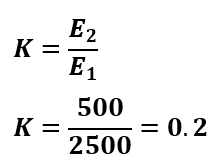
The voltage transformation ratio(K) of the transformer is,
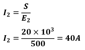
The secondary current of the transformer is.
Now, we will find the equivalent resistance and reactance at the secondary side of the transformer.
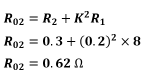
The equivalent secondary resistance referring the primary resistance to the secondary side,
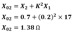
The equivalent secondary reactance referring the primary reactance to the secondary side,
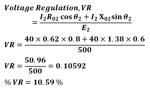
(a) Voltage regulation and secondary terminal voltage at 0.8 pf lagging
Voltage regulation at 0.8 pf lagging
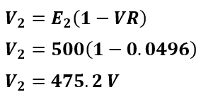
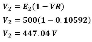
The secondary terminal voltage at 0.8 pf lagging
(b) Voltage regulation and secondary terminal voltage at 0.8 pf leading
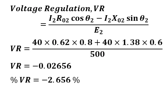
Points to be noted::
- Negative voltage regulation can only occur with leading power factor loads, however, not all leading loads will cause negative voltage regulation.
- Negative Voltage Regulation means the secondary terminal voltage increases with the load.
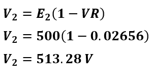
The secondary terminal voltage at 0.8 pf leading
(c) Voltage regulation and secondary terminal voltage at unity pf
Voltage regulation at the unity power factor
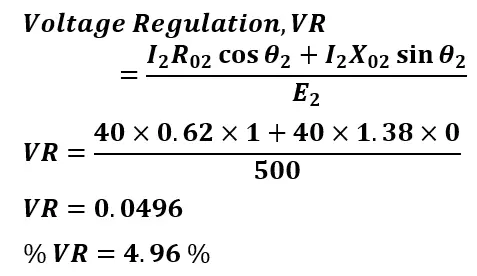
The secondary terminal voltage at the unity power factor