An ideal op amp is a differential amplifier that amplifies the voltage difference between its inverting and non-inverting input terminals. It has theoretically perfect characteristics, such as infinite open-loop gain, infinite input impedance, zero output impedance, and infinite bandwidth. These properties are used to describe the behaviour of an ideal operational amplifier.
What Is an Ideal Op Amp?
An ideal op amp (ideal operational amplifier) is a differential voltage amplifier that responds to the difference between the voltages applied at its two input terminals. It has perfect operating characteristics, such as infinite voltage gain, infinite input resistance, and zero output resistance, with no signal distortion or loading effect.
An ideal operational amplifier has two input terminals: an inverting terminal (−) and a non-inverting terminal (+). It also has one output terminal. The output voltage depends on the difference between the voltages applied to these two input terminals.
Unlike a practical operational amplifier, an ideal op amp is assumed to have no electrical limitations. Its characteristics are used as a reference for understanding op-amp circuits and simplifying the analysis of amplifier configurations.
The output voltage of an ideal operational amplifier is expressed as:
Where:
- = Output voltage
- = Open-loop voltage gain
- = Voltage at the non-inverting input
- = Voltage at the inverting input
An ideal op amp has infinite open-loop gain, so even a small voltage difference between its two input terminals can cause a significant change in the output voltage. When negative feedback is applied, the voltage difference between the inputs becomes nearly zero during normal operation.
Ideal Op Amp Characteristics
An ideal operational amplifier has some special characteristics that are different from those of a practical operational amplifier. These characteristics help us understand its working and make the analysis of different op amp circuits easier.
The following table summarizes the main characteristics of an ideal op amp.
| Characteristic | Ideal Value |
| Open-loop voltage gain | Infinite (∞) |
| Input resistance | Infinite (∞) |
| Output resistance | Zero (0 Ω) |
| Bandwidth | Infinite (∞) |
| Input impedance | Infinite |
| Input current | Zero (0 A) |
| Input offset voltage | Zero (0 V) |
| Common-mode rejection ratio (CMRR) | Infinite (∞) |
| Power supply rejection ratio (PSRR) | Infinite (∞) |
| Slew rate | Infinite |
| Noise | Zero |
Let’s understand these ideal operational amplifier characteristics in detail.
1. Infinite Open-Loop Gain
An ideal operational amplifier has infinite open-loop voltage gain. Open-loop gain is the amplification of an operational amplifier when no feedback is connected between its output and input terminals.
The open-loop voltage gain is given by:
For an ideal op amp:
This means that even a very small voltage difference between the two input terminals can produce an extremely large output voltage in an ideal operational amplifier. But in a practical operational amplifier, the output voltage cannot exceed its power supply voltage
2. Infinite Input Resistance
An ideal op amp has infinite input resistance at both input terminals. This means that it does not draw any current from the input signal source.
Input resistance is the opposition offered by an amplifier to the current flowing into its input terminals.
It is expressed as:
For an ideal op amp:
Therefore:
Where:
- = Current entering the non-inverting terminal.
- = Current entering the inverting terminal.
Since the input resistance is infinite, no current flows into the input terminals. Therefore, they behave like an open circuit, and the operational amplifier does not draw current from or affect the input signal source.
3. Zero Output Resistance
An ideal op amp has zero output resistance. Due to this, the output voltage does not change with the load connected to its output terminal, and there is no voltage drop inside the amplifier.
Output resistance is the internal resistance of an amplifier that opposes the flow of current from its output terminal to the connected load.
For an ideal op amp:
Therefore, an ideal operational amplifier can supply current to the connected load without any voltage drop across its output resistance. As a result, the output voltage remains unaffected by internal resistance losses.
4. Infinite Bandwidth
An ideal op amp has infinite bandwidth, which means its voltage gain remains the same at all frequencies, starting from DC (zero frequency) up to infinitely high frequencies.
For an ideal op amp:
An ideal operational can amplify signals of any frequency without any reduction in gain or phase shift. However, practical operational amplifiers have limited bandwidth due to their internal capacitances and frequency compensation circuits.
5. Zero Input Offset Voltage
An ideal op amp has zero input offset voltage. It means that no additional DC voltage difference is required between the inverting and non-inverting input terminals to make the output voltage zero.
For an ideal op amp:
When the same voltage is applied to both input terminals, an ideal op amp produces zero output voltage. However, in practical op amps, slight variations in the internal transistor characteristics can cause a small offset voltage at the output.
6. Infinite Common-Mode Rejection Ratio (CMRR)
An ideal operational amplifier has an infinite common-mode rejection ratio (CMRR). It means that the amplifier can completely reject signals that are applied equally to both input terminals.
It is expressed as:
Where:
- = Differential voltage gain.
- = Common-mode voltage gain.
For an ideal op amp:
This means that the opertaional amplifier rejects all common signals present at both input terminals and amplifies only the difference between the two input voltages.
7. Infinite Slew Rate
An ideal op amp has an infinite slew rate. Slew rate is the maximum speed at which the output voltage can change with time.
It is expressed as:
For an ideal op amp:
This means that the output voltage of an ideal op amp can change instantly when the input signal changes. In practical op amps, the slew rate is limited, which may cause distortion when amplifying high-frequency or large-amplitude signals.
8. Infinite Power Supply Rejection Ratio (PSRR)
An ideal op amp has an infinite power supply rejection ratio (PSRR). It means that changes in the supply voltage do not affect the output voltage of the amplifier.
For an ideal op amp:
This means that changes in the positive or negative supply voltage have no effect on the amplifier’s output characteristics.
9. Zero Noise
An ideal op amp does not produce any internal electrical noise. Noise is an unwanted electrical signal that can affect the original input signal and cause errors in the output.
For an ideal op amp:
Therefore, an ideal op amp produces an output signal without adding any noise of its own. However, practical op amps generate a small amount of voltage and current noise due to their internal semiconductor components.
Ideal Op Amp Diagram
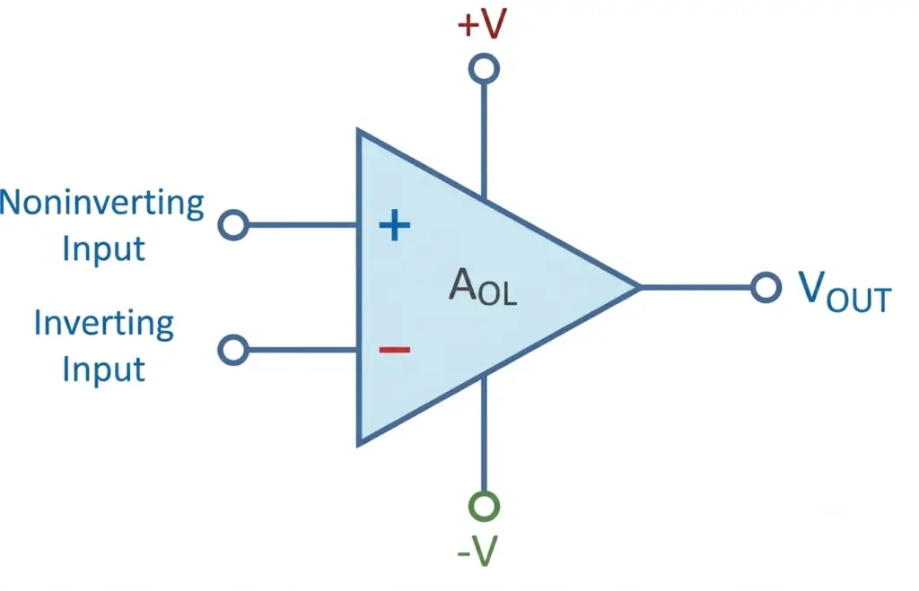
An ideal operational amplifier has three main signal terminals:
- Inverting input (−): The input signal applied to this terminal produces an inverted output response.
- Non-inverting input (+): The input signal applied to this terminal produces a non-inverted output response.
- Output terminal: Provides the amplified output voltage.
The op amp also has positive and negative power supply connections, which provide the energy required for its operation.
Working Principle of an Ideal Op Amp
The working principle of an ideal op amp is based on differential voltage amplification. It amplifies the voltage difference between its inverting and non-inverting input terminals.
The output voltage is determined by:
There are three possible input conditions.
Case 1: Non-Inverting Input Voltage Is Higher
When the voltage at the non-inverting terminal is greater than the voltage at the inverting terminal:
The output voltage becomes positive and moves towards positive saturation.
Case 2: Inverting Input Voltage Is Higher
When the voltage at the inverting terminal is greater than the voltage at the non-inverting terminal:
The output voltage becomes negative and moves towards negative saturation.
Case 3: Both Input Voltages Are Equal
When both input terminals have equal voltages:
The differential input voltage becomes zero.
Therefore, the output voltage is zero under ideal conditions.
Important: In an operational amplifier circuit using negative feedback, the voltage at both input terminals is nearly equal. This condition is called a virtual short. However, the two input terminals are not physically connected to each other.
Virtual Short Concept in an Ideal Op Amp
The virtual short concept is one of the most important principles used in ideal op amp circuit analysis.
Since an ideal operational amplifier has infinite open-loop gain, negative feedback makes the voltage difference between its two input terminals almost zero during normal operation.
Therefore:
This condition is commonly called a virtual short because both input terminals have the same voltage, even though they are not physically connected.
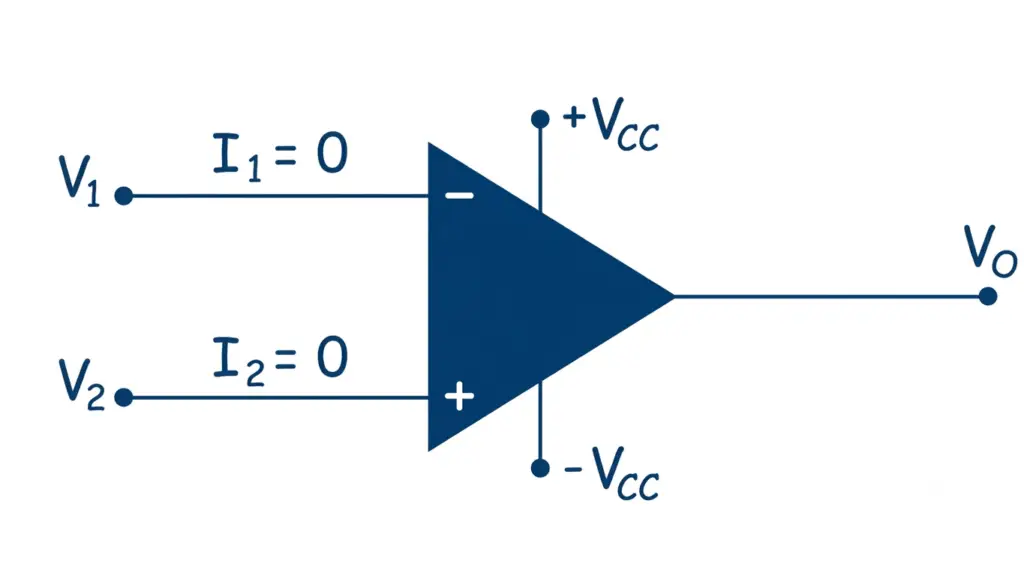
Another important assumption is that no current flows into either input terminal:
These two assumptions are commonly used to make the analysis of inverting, non-inverting, summing, and other op amp circuits easier.
Ideal Op Amp vs Practical Op Amp
An ideal operational amplifier is a theoretical model, whereas a practical op amp is a physical electronic component with certain electrical limitations.
The following table highlights the major differences.
| Parameter | Ideal Op Amp | Practical Op Amp |
| Open-loop gain | Infinite | Very high but finite |
| Input resistance | Infinite | High but finite |
| Output resistance | Zero | Low but non-zero |
| Bandwidth | Infinite | Limited |
| Input current | Zero | Very small |
| Input offset voltage | Zero | Small non-zero value |
| CMRR | Infinite | High but finite |
| PSRR | Infinite | High but finite |
| Slew rate | Infinite | Finite |
| Noise | Zero | Present |
| Temperature effects | None | Present |
Conclusion
An ideal op amp has certain perfect electrical characteristics, such as infinite open-loop gain, infinite input resistance, zero output resistance, infinite bandwidth, zero input offset voltage, and infinite CMRR.
These properties are useful for understaanding the working of different op amp circuits, including amplifiers, filters, integrators, and differentiators. In practical op amps, these characteristics are not achieved completely, but their design aims to get as close as possible to the ideal values.
Read Next: