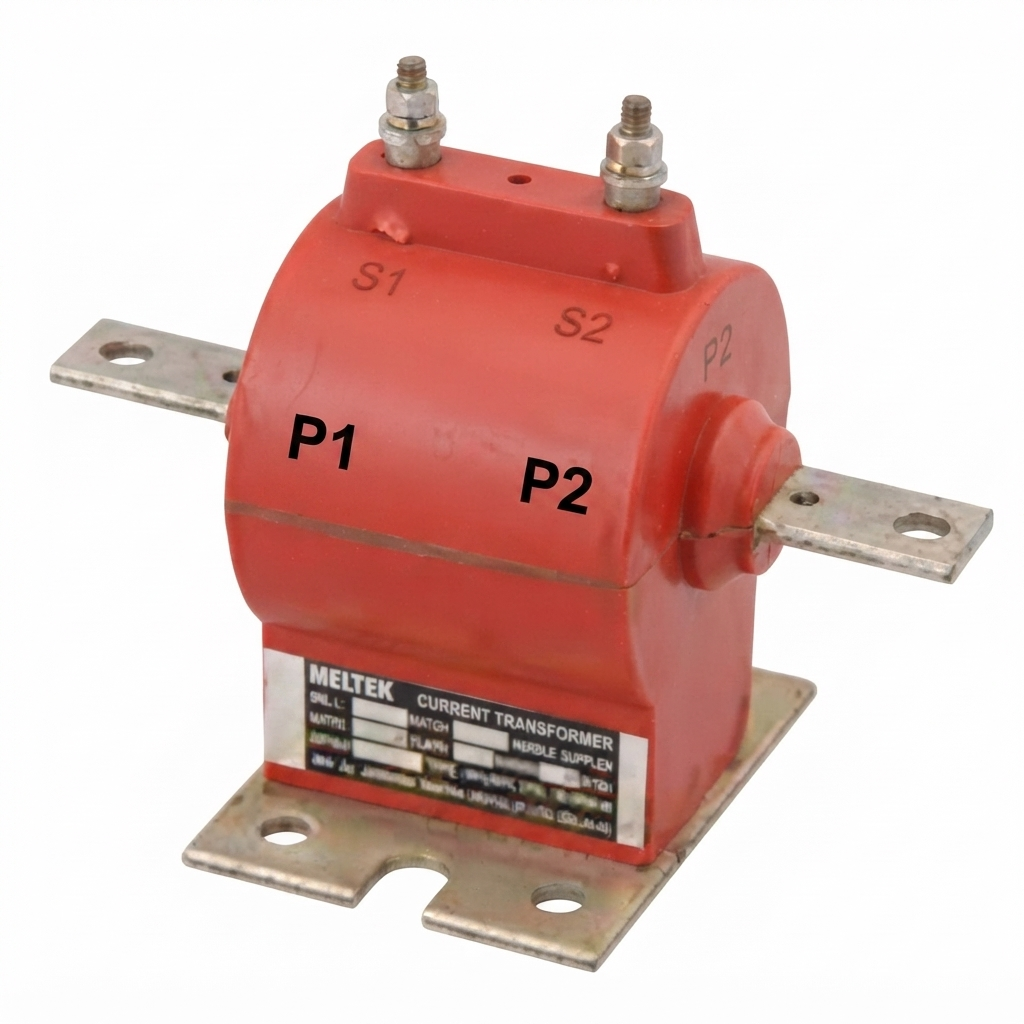
A Bar Primary CT is a type of current transformer (CT) in which a solid conductor or bar forms the primary winding. The primary bar passes through the magnetic core, while the secondary winding is wound around the core to produce a reduced current proportional to the primary current.
Unlike other categories in types of current transformers, a bar type current transformer uses a solid bar as its primary conductor, which provides a simple and robust construction for measuring current and maintaining a fixed turns ratio. It is therefore particularly suitable for high-current measurement, metering, and protection applications in switchgear, substations, motor control centers, and industrial power systems.
Construction of Bar Primary CT
A Bar Primary CT consists of a magnetic core, a secondary winding, insulation system, and an integral primary conductor or bar. The construction provides mechanical strength and allows the CT to withstand high short-circuit currents.
1. Magnetic Core
The magnetic core provides a low-reluctance path for the magnetic flux produced by the primary current.
- Made from laminated electrical steel or other magnetic materials.
- Laminations reduce eddy current losses.
- Provides a low-reluctance path for magnetic flux.
- The core design determines the CT’s accuracy, excitation characteristics, and saturation behavior.
- Protection CTs may use cores designed to maintain performance during high fault currents.
2. Primary Bar
The primary bar is the most distinctive part of a Bar Primary CT.
- Consists of a solid copper or aluminium conductor.
- Usually forms one primary turn.
- Connected directly in series with the power circuit.
- Carries the full primary current.
- Designed to withstand continuous load current and short-circuit forces.
- The bar may be insulated depending on the system voltage and CT construction.
3. Secondary Winding
The secondary winding consists of multiple turns of fine insulated conductor wound around the magnetic core.
- Produces a reduced current proportional to the primary current.
- Common secondary ratings are 1 A or 5 A.
- Connected to meters, measuring instruments, or protective relays.
- The number of secondary turns determines the effective transformation ratio when the primary has one turn.
4. Insulation System
The insulation system electrically separates the primary conductor from the secondary winding and core.
- May use epoxy resin, molded insulation, paper insulation, or other suitable insulating materials.
- Provides electrical insulation between primary and secondary circuits.
- Protects internal components against moisture, contamination, and mechanical damage.
- Helps maintain dielectric strength during normal operation and fault conditions.
Working Principle of Bar Primary CT
A Bar Primary CT works on the principle of electromagnetic induction.
When alternating current flows through the primary bar, it produces an alternating magnetic flux in the CT core. This magnetic flux links with the secondary winding and induces a secondary current proportional to the primary current.
For an ideal current transformer:
Where:
Ip= Primary currentIs= Secondary currentNp= Number of primary turnsNs= Number of secondary turns
Since a typical Bar Primary CT has one primary turn:
Therefore, the approximate current ratio becomes:
For example, if a CT has a 1000/5 A ratio, a primary current of 1000 A produces approximately 5 A on the secondary under ideal conditions.
Key Working Points
- The primary bar is connected in series with the electrical circuit.
- The primary normally consists of one turn.
- The secondary produces a scaled-down current.
- The CT provides electrical isolation between the high-current primary circuit and measuring/protection equipment.
- The CT ratio depends mainly on the primary and secondary turns.
- The primary bar must be properly rated for both continuous and short-circuit current.
⚠️ Safety Warning (IMPORTANT): Never leave the secondary circuit of an energized current transformer open. An open CT secondary can develop a dangerously high voltage, which may cause insulation failure, arcing, equipment damage, or serious injury. Always keep the secondary connected to its burden or safely short-circuited when required.
Key Features of Bar Primary CT
A Bar Primary CT offers several features that make it suitable for high-current applications.
- Solid primary conductor provides high mechanical strength.
- Usually has a single primary turn.
- Suitable for high primary current ratings.
- Provides good short-circuit withstand capability.
- Available for both metering and protection applications.
- Compact compared with some wound-primary CT constructions.
- Provides electrical isolation between the primary circuit and secondary instruments.
- Can be integrated into switchgear and other power equipment.
Technical Specifications of Bar Primary CT
The electrical, insulation, thermal, and mechanical specifications of a Bar Primary CT depend on its design and application. Typical specifications include the following.
Electrical Specifications
- Primary Current: Commonly available from several hundred amperes to several thousand amperes, depending on the application.
- Secondary Current: Standard secondary ratings are generally 5 A or 1 A.
- Current Ratio: Typical ratios include 100/5 A, 200/5 A, 400/5 A, 600/5 A, 800/5 A, 1000/5 A, 1500/5 A, and higher ratings.
- Rated Burden: The CT burden may range from a few VA to several tens of VA depending on the CT application.
- Accuracy Class: Metering CTs may use classes such as 0.2, 0.5, 1.0, and 3.0, while protection CTs may use classes such as 5P and 10P.
- Protection Class: Protection CTs may be specified using combinations such as 5P10, 5P20, 10P10, and 10P20, depending on the protection scheme.
- Knee Point Voltage (KPV): Protection CTs used with differential and high-impedance protection schemes are specified by their Knee Point Voltage (KPV). Typical values range from 50 V to several hundred volts, depending on the protection relay requirements and CT design.
- Frequency: Normally designed for 50 Hz or 60 Hz systems.
System and Insulation Specifications
The insulation requirements depend strongly on the system voltage and CT construction.
- System Voltage: Bar CTs are available for low-voltage, medium-voltage, and higher-voltage applications.
- Power-Frequency Withstand Voltage: Selected according to the applicable insulation level.
- Insulation Type: May include epoxy-resin, molded, or other suitable insulation systems.
- Impulse Withstand Voltage: High-voltage CTs may be specified for a particular lightning impulse withstand level.
- Insulation Resistance: Should remain within the manufacturer’s specified limits during commissioning and maintenance.
Thermal and Mechanical Specifications
Because the primary bar carries the full system current, thermal and mechanical ratings are particularly important.
- Continuous Thermal Current: The CT should withstand its rated primary current continuously without exceeding the specified temperature rise.
- Short-Time Thermal Current (Ith): Defines the short-circuit current that the CT can withstand for a specified duration, commonly 1 second or 3 seconds.
- Dynamic Current Rating (Idyn): Defines the CT’s ability to withstand the mechanical forces produced by high peak fault currents.
- Primary Bar Size: Selected according to the rated current and installation arrangement.
- Construction: May be molded, epoxy-cast, or designed as part of switchgear equipment.
- Applicable Standards: Current transformers are commonly designed and tested according to standards such as IEC 61869-2 and IEEE C57.13, as applicable.
Installation and Maintenance of Bar Primary CT
Correct installation and regular maintenance are essential for maintaining the accuracy, insulation strength, and reliability of a Bar Primary CT.
Installation Guidelines
- Install the CT according to the manufacturer’s instructions.
- Ensure that the primary bar is correctly positioned and securely connected.
- Verify the CT polarity markings, such as P1 and P2.
- Connect the secondary terminals according to the specified polarity, such as S1 and S2.
- Tighten primary and secondary connections to the specified torque.
- Select the CT with the correct ratio, burden, accuracy class, and thermal rating.
- Ensure adequate clearance and creepage distance for the applicable system voltage.
- Keep the CT clean and protected from excessive moisture, dust, and corrosive contaminants.
- Never leave the secondary circuit open while the primary circuit is energized.
- Verify that the CT secondary circuit is correctly connected to the meter, relay, test terminal block, or shorting arrangement.
Maintenance Guidelines
Regular inspection helps identify problems before they affect measurement or protection performance.
- Inspect the CT body and insulation for cracks, damage, or discoloration.
- Check primary and secondary terminals for looseness or overheating.
- Clean accumulated dust and contamination from accessible surfaces.
- Measure insulation resistance during scheduled maintenance.
- Verify CT ratio and polarity when required.
- Check secondary wiring for loose connections and damaged insulation.
- Inspect connected meters and protection relays for abnormal indications.
- Check for excessive heating at primary connections using appropriate inspection methods.
- Replace the CT if severe insulation deterioration, physical damage, or other major defects are detected.
Common Problems and Troubleshooting
| Problem | Possible Cause | Solution |
| Incorrect current measurement | Incorrect CT ratio, polarity, or loose secondary connection | Verify the CT ratio, polarity, and secondary wiring |
| CT overheating | Excessive primary current, loose connection, or excessive burden | Check the load current, connections, and connected burden |
| Core saturation | High fault current or unsuitable protection CT | Select a CT with an appropriate accuracy class and ALF |
| Relay malfunction | CT saturation, incorrect polarity, or wiring error | Check CT specifications, polarity, and secondary circuit |
| High secondary voltage | Secondary circuit left open | De-energize safely and reconnect or short the secondary |
| Insulation failure | Moisture, contamination, aging, or excessive electrical stress | Perform insulation testing and replace the CT if necessary |
| Ratio error | Incorrect CT selection or excessive burden | Verify the CT ratio and ensure the connected burden is within the rated value |
| Hot primary connection | Loose or poorly tightened primary terminal | Inspect and tighten the connection according to the manufacturer’s specification |
Bar Primary CT – Burst Risk and Safety
A Bar Primary CT generally provides strong mechanical construction because the primary conductor is a solid bar rather than a finely wound primary winding. However, improper installation, excessive fault current, insulation failure, or an open secondary can still create serious hazards.
During a short circuit, the primary bar experiences extremely high current and therefore significant thermal and electromagnetic forces. If the CT is not correctly rated for the system’s short-circuit conditions, excessive heating and mechanical stress can damage the primary conductor, insulation, or core assembly.
An open secondary circuit presents another major safety risk. When the primary is energized, the CT attempts to maintain the magnetic balance required by transformer action. With the secondary open, the magnetic flux and induced secondary voltage can rise to dangerous levels.
Therefore, the CT secondary must never be left open while the primary is energized. Proper shorting facilities should be provided wherever the secondary circuit may need to be disconnected for testing or maintenance.
Applications of Bar Primary CT
Bar Primary CTs are widely used where the electrical system carries high current and reliable measurement or protection is required.
Common applications include:
- Switchgear for current measurement and protection.
- Substations for metering and protective relay applications.
- Motor control centers (MCCs) for monitoring large motor currents.
- Industrial distribution systems for current measurement.
- Generator protection systems for detecting overloads and faults.
- Transformer protection and metering applications.
- Energy metering systems for measuring electrical consumption.
- Overcurrent protection systems.
- Earth-fault protection when appropriately configured.
- Differential protection schemes using suitable protection-class CTs.
- Power monitoring systems connected to multifunction meters and power analyzers.
- SCADA and automation systems requiring current signals.
- High-current feeder circuits where a solid primary conductor is advantageous.
Advantages of Bar Primary CT
A Bar Primary CT offers several advantages for high-current electrical systems.
- Suitable for high-current applications.
- Strong mechanical construction.
- Solid primary conductor can withstand high fault currents when properly rated.
- Simple primary construction.
- Good electrical isolation between primary and secondary circuits.
- Available in metering and protection configurations.
- Compact and convenient for integration into switchgear.
- Suitable for industrial and power distribution systems.
- Requires no separate primary winding installation when the integral bar forms the primary conductor.
Limitations of Bar Primary CT
Despite its advantages, a Bar Primary CT has some limitations.
- Usually has a fixed primary turn.
- Less flexible in primary turns ratio than a wound-primary CT.
- Physical dimensions of the primary bar can limit installation flexibility.
- Very high-voltage applications require more complex insulation arrangements.
- Incorrect selection of burden or accuracy class can affect measurement and protection performance.
- Replacement can be more difficult when the CT is integrated into switchgear.
- The primary conductor must be appropriately rated for continuous and short-circuit currents.
Bar Primary CT vs Other CT Types
| Feature | Bar Primary CT | Wound CT | Window CT |
| Primary Construction | Solid bar | Wound conductor | External cable or busbar |
| Typical Primary Turns | Usually one | One or more | Depends on conductor passes |
| Current Range | Medium to high | Low to medium | Medium to high |
| Primary Flexibility | Limited | High | Flexible |
| Mechanical Strength | High | Moderate | High |
| High-Current Application | Excellent | Limited | Excellent |
| Metering | Suitable | Highly suitable | Suitable |
| Protection | Highly suitable | Suitable | Highly suitable |
| Installation | Integrated/series connection | Series connection | Conductor passes through window |
| Typical Application | Switchgear, substations, feeders | Instrumentation, metering | Distribution and protection |
Bar Primary CT vs Wound CT
The primary difference between a Bar Primary CT and a Wound CT is the construction of the primary winding.
A Bar Primary CT uses a solid conductor or bar as the primary, generally with one primary turn. It is therefore well suited to high-current applications and provides strong mechanical resistance to short-circuit forces.
A Wound CT, in contrast, uses a physically wound primary conductor with one or more turns. This arrangement provides greater flexibility in selecting the primary turns ratio and is particularly useful for lower-current applications requiring accurate measurement.
Bar Primary CT Ratio
The current ratio of a Bar Primary CT is determined by the relationship between its primary and secondary turns.
For a typical single-turn primary:
The ideal CT ratio is:
For example, consider a 500/5 A Bar Primary CT.
The transformation ratio is:
Thus, when the primary current is 500 A, the secondary current is approximately 5 A under ideal conditions.
If the primary current falls to 250 A:
Therefore, a 250 A primary current produces approximately 2.5 A secondary current.
Factors Affecting Bar Primary CT Accuracy
The accuracy of a Bar Primary CT depends on several electrical and operating conditions.
1. CT Burden
A burden higher than the rated value can increase the CT’s errors and affect the secondary voltage requirement.
2. Core Saturation
During high fault currents, the magnetic core may approach saturation. Saturation can distort the secondary current and affect protective relay operation.
3. CT Ratio
Selecting an inappropriate current ratio can reduce measurement accuracy, particularly when the normal operating current is significantly lower than the CT’s rated primary current.
4. Secondary Wiring
Long secondary cables have resistance and therefore increase the total burden. Proper cable sizing helps maintain CT performance.
5. Accuracy Class
The CT should have an accuracy class appropriate for its intended function. Metering and protection applications may require different CT characteristics.
6. Installation Conditions
Loose connections, contamination, excessive temperature, and mechanical damage can affect CT performance and reliability.
How to Select a Bar Primary CT
Select a Bar Primary CT by considering the following parameters:
- Primary current rating
- Secondary current rating
- Current transformation ratio
- System voltage
- Frequency
- Accuracy class
- Rated burden
- Short-time thermal current
- Dynamic current rating
- Protection requirements
- Installation dimensions
- Insulation level
- Metering or protection application
- Applicable standards
For protection applications, the CT’s Accuracy Limit Factor (ALF) and excitation characteristics should also be checked to ensure suitable performance during fault conditions.
Conclusion
A Bar Primary CT is a robust current transformer designed primarily for medium- and high-current electrical systems. Its solid primary bar normally forms a single primary turn, while the secondary winding produces a proportional, reduced current for measurement and protection.
Its strong mechanical construction, high-current capability, simple primary arrangement, and suitability for switchgear and substations make it an important component in industrial and power distribution systems.
However, correct selection of the CT ratio, accuracy class, burden, insulation level, thermal rating, and short-circuit withstand capability is essential for reliable operation. As with all current transformers, the secondary circuit must never be left open while the primary is energized.
When properly selected, installed, and maintained, a Bar Primary CT provides reliable current measurement and dependable input for electrical protection systems.
Read Next:
- Current Transformer (CT): Definition, Working and Applications
- Types of Current Transformers (CT)
- Difference between Current Transformer(CT) & Potential Transformer(PT)
- Core Balance Current Transformer(CBCT)
- Accuracy Limit Factor of Current Transformer
- Wound Current Transformer (WCT)
- Window Current Transformer: Construction, Working & Applications