An electrical transformer is a static electrical device that transfers electrical energy by increasing or decreasing AC voltage and current without changing its frequency. It works on the principle of Faraday’s Law of Electromagnetic Induction.
There are various types of transformers designed for power generation, transmission, distribution, industrial, and electronic applications. These transformers are classified based on parameters such as voltage conversion, application, phase, core construction, insulation method, winding configuration, and core material.
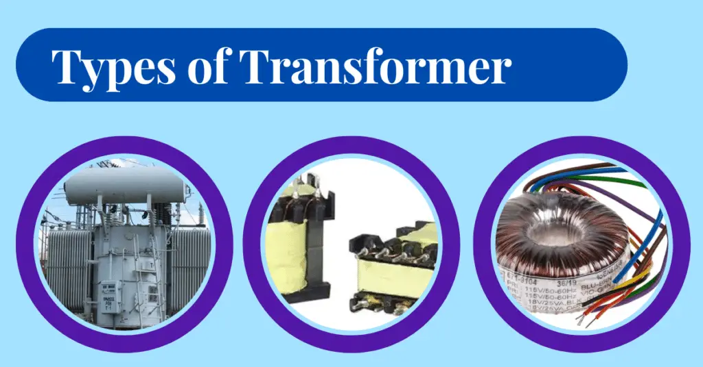
In this guide, you will learn about the 20 most common types of transformers, their working principles, applications, and key features.
Different Types of Transformers
The main types of transformers are listed below:
- Step-Up Transformer
- Step-Down Transformer
- Power Transformer
- Distribution Transformer
- Isolation Transformer
- Instrument Transformer
- Single-Phase Transformer
- Three-Phase Transformer
- Core-Type Transformer
- Shell-Type Transformer
- Berry-Type Transformer
- Air-Core Transformer
- Ferrite-Core Transformer
- Toroidal Transformer
- Oil-Filled Transformer
- Dry-Type Transformer
- Two-Winding Transformer
- Auto Transformer
- Earthing Transformer
- Pulse Transformer
The following sections explain each types of transformer in detail.
1. Step Up Transformer
A step-up transformer increases the input voltage by converting the low voltage applied to the primary winding into a higher voltage at the secondary winding.
It has fewer turns in the primary winding and more turns in the secondary winding. This winding arrangement increases the input voltage, producing an output voltage that is higher than the input voltage.
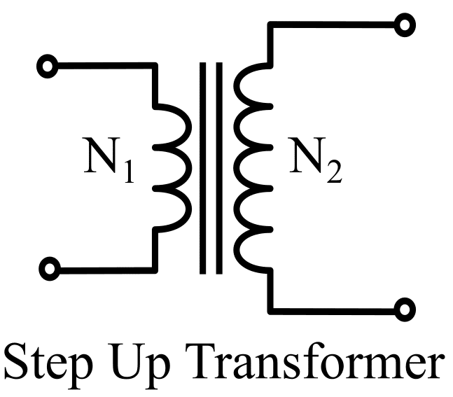
For a step-up transformer, the following relation exists,
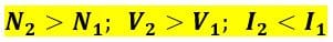
Where N1 and N2 are the primary and secondary winding turns respectively, V1 and V2 are the primary and secondary voltage respectively, and I1 and I2 are the primary and secondary current respectively.
Step-up transformers are used in the voltage stabilizers & inverters. A step-up transformer is used to boost the voltage for the transmission of power to reduce transmission losses.
The step-up transformer boosts the voltage in the electrostatic precipitator (ESP) to remove the dust and particles from the dust-laden gas.
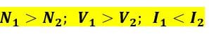
2. Step Down Transformer
A step-down transformer converts a high primary voltage into a lower secondary voltage. It has a greater number of turns in the primary winding than in the secondary winding, so the primary-to-secondary turns ratio is always greater than one.
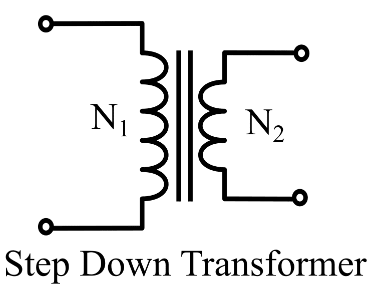
For a step-down transformer, the following relation exists,
Step-down transformers are widely used in electrical and electronic applications. Most electronic circuits require low operating voltages such as 5 V, 6 V, 9 V, 12 V, 24 V, and 48 V. A step-down transformer converts the 230 V AC single-phase supply to the required AC voltage level, which is then converted into DC by a rectifier circuit. Therefore, step-down transformers are widely used in the power adapters of electronic devices.
3. Power Transformer
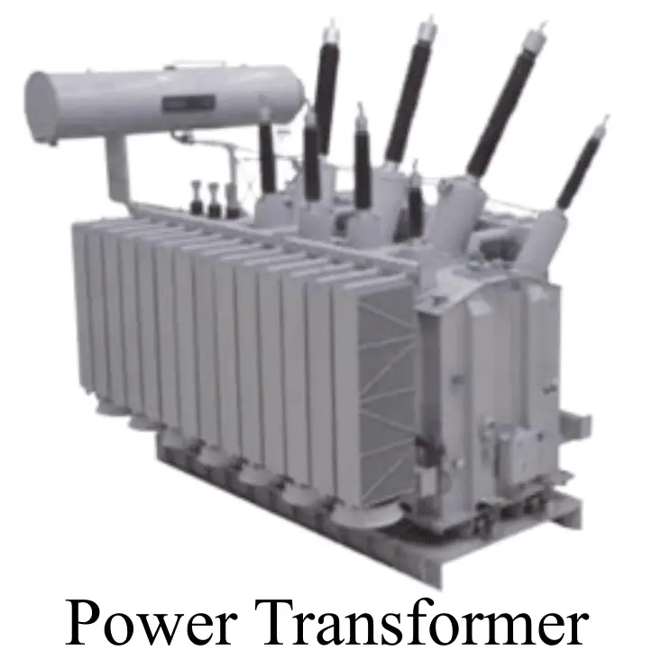
Power transformers are the type of transformer that is primarily designed to operate at an almost constant load, close to their rated kVA capacity. They achieve maximum efficiency at or near full-load conditions. Therefore, power transformers are primarily used in power generation stations and high-voltage transmission systems. In most power transformers, both the primary and secondary windings are connected in a delta configuration.
4. Distribution Transformer
A distribution transformer is designed to provide the final voltage transformation in the electrical power distribution system before electricity is supplied to consumers. It distributes electrical power to residential, commercial, and industrial loads by stepping down the distribution voltage to the required utilization voltage.
Distribution transformers are usually subjected to variable loads that are considerably lower than their rated load. Therefore, they are designed to achieve maximum efficiency at about 50% to 75% of their full-load capacity.
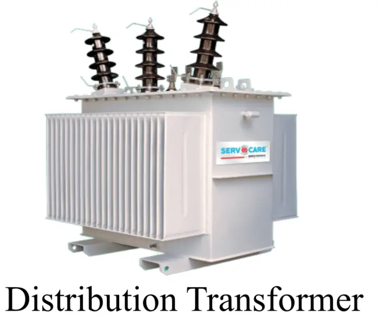
In a distribution transformer, the primary winding is generally connected in a delta configuration, while the secondary winding is connected in a star configuration.
Distribution transformers are available in a wide range of ratings to meet different load requirements. They commonly step down distribution voltages such as 11 kV, 6.6 kV, or 3.3 kV to utilization voltages such as 415 V, 400 V, 230 V, or other standard supply voltages, depending on the distribution system.
5. Isolation Transformer
An electrical transformer that has an equal number of turns in both primary winding and secondary winding is called a one-to-one transformer (1:1 transformer). It is also known as an isolation transformer, which is a type of transformer, mainly used to isolate two circuits electrically while transmitting power magnetically.
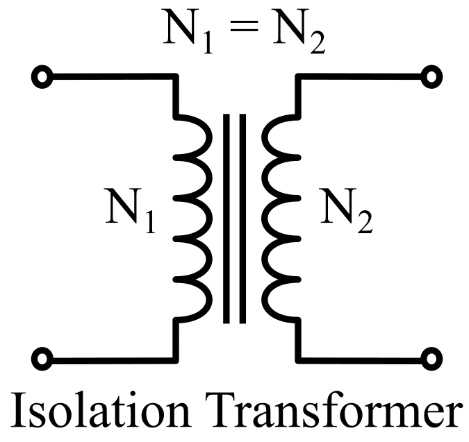
For an isolation transformer,
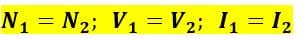
The isolation transformer, like other transformers, electrically isolates the primary and secondary. The turn ratio of the isolation transformer is unity and thus the secondary voltage is equal to the primary voltage. The isolation transformer provides impedance to surge voltage & transients and thus it protects sensitive electronic equipment.
The isolation transformer, like other transformers, provides electrical isolation between the primary and secondary windings. The turn ratio of the isolation transformer is unity, and thus the secondary voltage is equal to the primary voltage. It provides galvanic isolation and impedance to surge voltages and transients, thereby protecting sensitive electronic equipment.
In addition to isolation, it helps in reducing electrical noise, suppressing voltage surges, and protecting sensitive electronic equipment from transients. This makes it highly useful in applications where safety and signal integrity are important.
Isolation transformers are commonly used in computers, measuring instruments, medical equipment, and power electronic devices to ensure safe operation and prevent electric shock hazards.
6. Instrument Transformer
Instrument transformers are high-precision devices designed to scale down voltage or current levels in a power system for safe measurement and protection purposes. They are widely used to monitor electrical parameters such as current, voltage, power, frequency, and power factor with high accuracy.
These transformers also play an important role in system protection by working in coordination with protective relays. In their operation, the primary winding is connected directly to the high-voltage or high-current circuit, while the secondary winding supplies a reduced and safe value to measuring instruments and relays.
Instrument transformers are generally compact to medium in size and are designed to deliver standardized secondary ratings, commonly around 5A for current and 100–200 V for voltage applications.
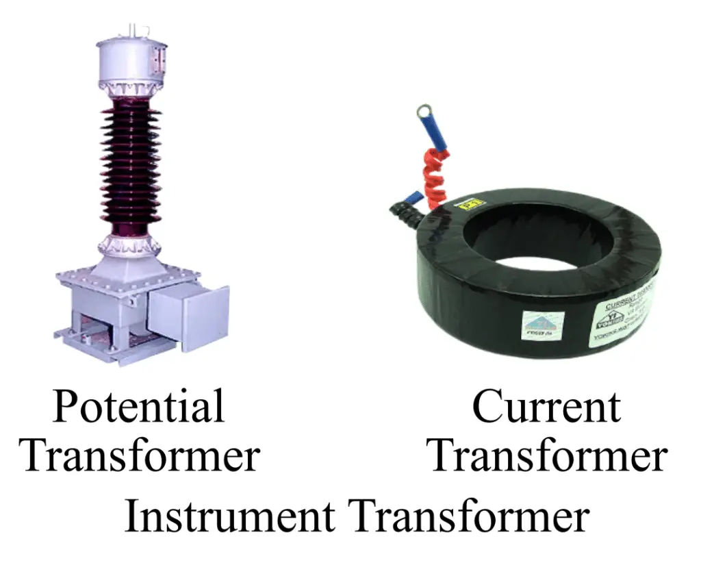
There are two types of instrument transformer:
- Current Transformer
- Potential Transformer
Current Transformer:
A current transformer (CT) is a type of instrument transformer widely used in AC power systems to step down high alternating current (AC) to a lower, measurable value. It produces a proportional reduced current in its secondary winding that accurately represents the primary current flowing in the power circuit.
These transformers are essential for both measurement and protection purposes. When the current in a system is too high to be directly applied to measuring instruments or protective relays, the current transformer safely scales it down to a standardized level, ensuring accurate readings and safe operation.
As an instrument transformer, a CT plays a vital role in power system monitoring and control. It is commonly installed in power stations, electrical substations, switchgear panels, and industrial plants. In addition to measurement, it also supports protective relays by detecting fault conditions and helping isolate abnormal currents in the system.
Potential Transformer (PT)
A potential transformer (PT), also known as a voltage transformer (VT), is a type of instrument transformer used in AC power systems to step down high voltage to a lower, safe, and measurable level. It produces a proportional reduced voltage in its secondary winding that accurately represents the primary high voltage in the system.
These transformers are mainly used for accurate measurement and protection of electrical networks. When the system voltage is too high to be directly applied to measuring instruments or protective relays, the potential transformer safely reduces it to a standardized value, ensuring precise readings and reliable operation of metering and protection devices.
As an instrument transformer, a PT plays a crucial role in monitoring system voltage, power, and overall grid performance. It is commonly installed in power stations, substations, switchgear panels, and industrial power distribution systems. In addition to measurement, it supports protective relays by supplying accurate voltage signals for fault detection and system safety.
Potential transformers are mainly of three types based on their construction and working principle: Optical PT, Electromagnetic (wire-wound) PT, and Capacitor Voltage Transformer (CVT). Optical PT uses light-based sensing for high-voltage measurement, while electromagnetic PT uses windings to step down voltage. CVT uses a capacitor divider with an electromagnetic unit to reduce extra-high transmission voltages for metering and protection.
7. Single-Phase Transformer
A single-phase transformer has one primary winding and one secondary winding. It is designed to operate on a single-phase AC supply and is commonly used in residential and light commercial applications. These transformers are widely found in devices such as battery chargers, microwave ovens, televisions, and other household electrical equipment.
A single-phase transformer has two input terminals connected to the primary winding and two output terminals connected to the secondary winding.
8. Three-Phase Transformer
A three-phase transformer consists of three primary windings and three secondary windings, with one set for each phase. The three-phase transformer connections, such as star-star (Y-Y), delta-delta (Δ-Δ), star-delta (Y-Δ), and delta-star (Δ-Y), are selected based on the required voltage level and application.
Instead of a single three-phase transformer, a bank of three single-phase transformers can also be used to perform the same function. Three-phase transformers are primarily used in power generation, transmission, and distribution systems, as well as in industrial, commercial, and large residential applications.
9. Core Type Transformer
An electrical transformer in which the primary winding and the secondary winding are placed around two different limbs of the core as shown in the following figure is called a core-type transformer.
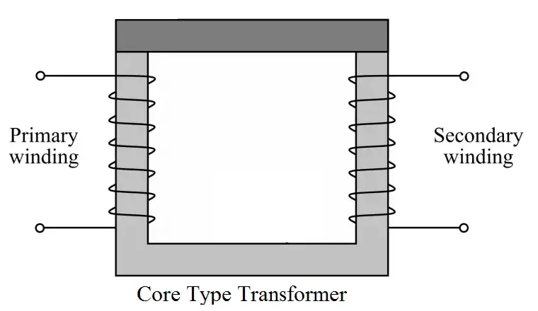
The iron core has excellent magnetic properties and there is minimum flux leakage and almost all the flux links to the primary and secondary winding and it has higher efficiency.
We can select the different types of core plates as per the requirements. The core plates are available in E, I, U, and L, shapes. The thin plates are bunched together to make a core to reduce the eddy current losses.
10. Shell Type Transformer
An electrical transformer in which both primary and secondary windings are wound around the central limb of the core is called a shell-type transformer. Shell type transformer is shown in the following figure.
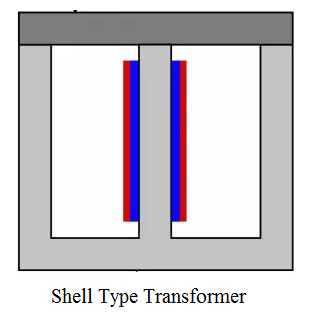
This type of transformer uses a double magnetic circuit. It is suitable for high voltage low current applications due to slightly poor ventilation.
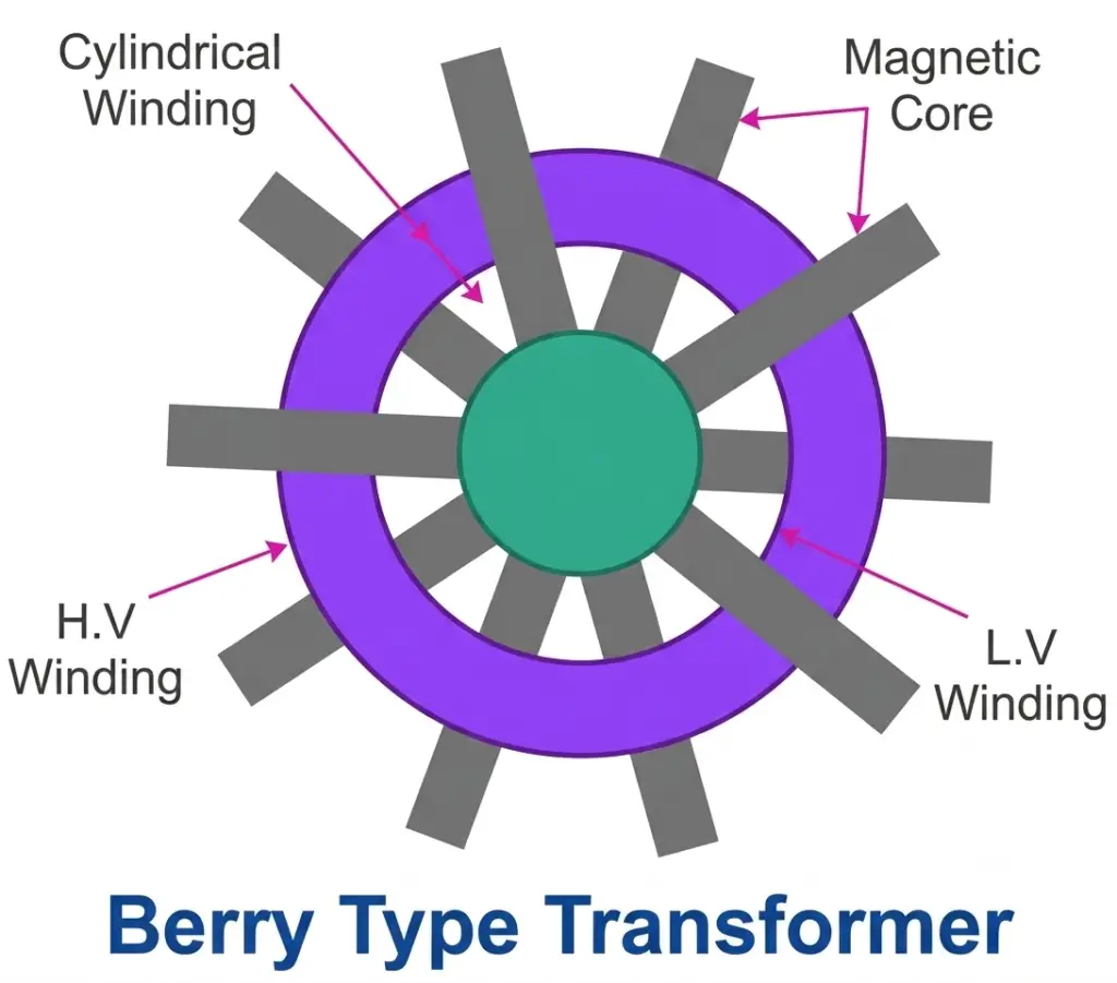
11. Berry Type Transformer
A Berry type transformer is a special form of shell-type transformer named after its designer. It features a cylindrical construction and a distributed magnetic core with more than two magnetic paths, unlike conventional shell-type transformers. The laminated core is arranged in a spoke-like pattern, similar to the spokes of a wheel, while the windings are wound in a cylindrical form around the core. This design provides multiple magnetic circuits for improved flux distribution.
12. Air Core transformer
The primary and secondary windings of an air core transformer are not wound on any magnetic material. The flux passes through air, and air acts as the core of the transformer.
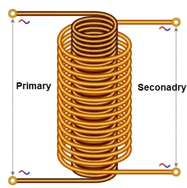
The air core transformer is a type of transformer in which both windings are placed on a non-magnetic medium. The flux linkage between the primary and secondary windings is established through air.
The air core transformer produces low mutual inductance compared to iron core and ferrite core transformers because the reluctance offered to magnetic flux in air is high.
These transformers are commonly used in small electronic devices, communication systems, and radio frequency (RF) circuits, such as antenna coils and transmission systems, where lightweight and low-loss operation is required.
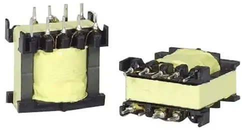
13. Ferrite Core Transformer
A transformer that has a ferrite core is called a ferrite core transformer.
Ferrite core transformers use a magnetic core made of ferrite on which the primary and secondary windings are placed. Ferrite cores have high magnetic permeability and low core losses at high frequencies.
These transformers are widely used in high-frequency applications because they offer very low losses during high-frequency operation. Due to this property, ferrite core transformers are extensively used in switch-mode power supplies (SMPS), RF (radio frequency) circuits, and other electronic applications.
Ferrite core transformers are available in different shapes and sizes depending on the application requirements.
14. Toroidal Core Transformer
A transformer that uses a toroid-shaped core made of materials such as iron or ferrite is called a toroidal transformer. A toroid is a ring or donut-shaped core, and it offers superior electrical performance.
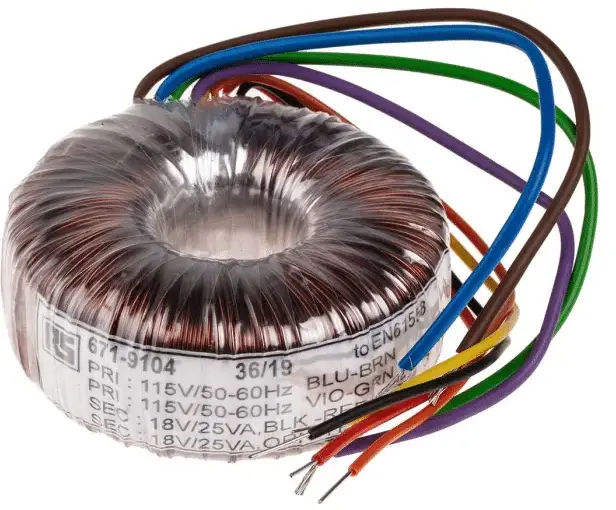
Due to its closed-loop design, the toroidal transformer has very low leakage inductance, high inductance, and high Q factor. This results in improved efficiency and better magnetic coupling compared to conventional core transformers.
These transformers are widely used in power supplies, inverters, amplifiers, and other electronic circuits where efficiency and compact design are important.
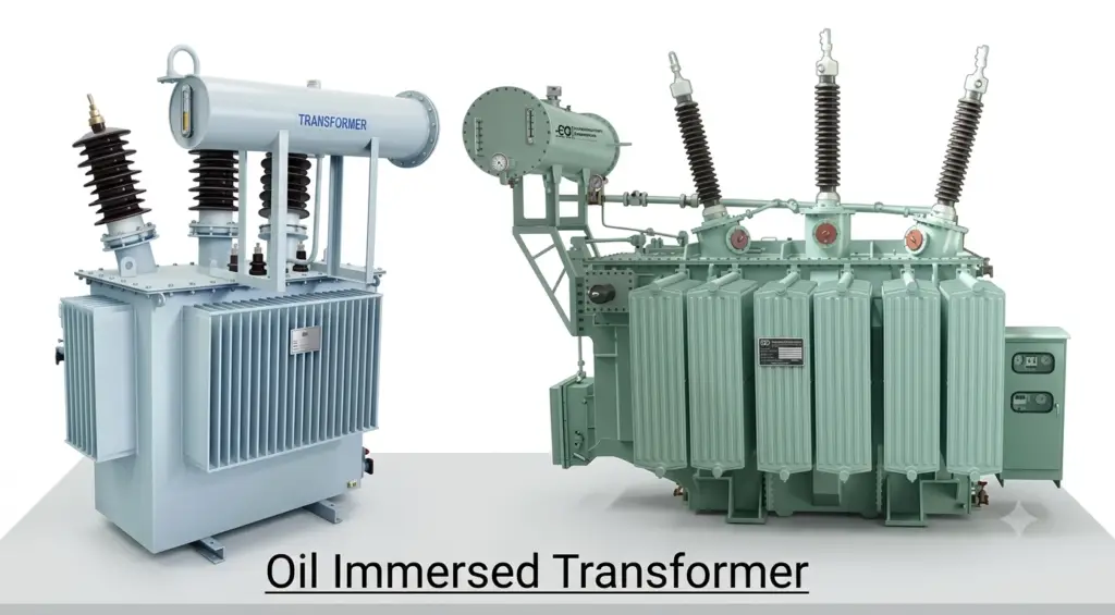
15. Oil-Filled Transformer
Oil-filled transformers use insulating mineral oil for both cooling and electrical insulation. During operation, the oil absorbs heat generated by the windings and core. The heated oil then circulates through radiators or heat exchangers, where it releases the heat before returning to the transformer. This continuous cooling process helps maintain a safe operating temperature and improves the transformer’s efficiency and service life.
16. Dry-Type Transformer
Dry-type transformers use air instead of insulating oil to dissipate heat generated during operation. Cooling is achieved through natural air circulation or by using cooling fans that force air through ventilation openings in the transformer’s enclosure. Since these transformers do not contain flammable oil, they offer improved fire safety and require less maintenance.
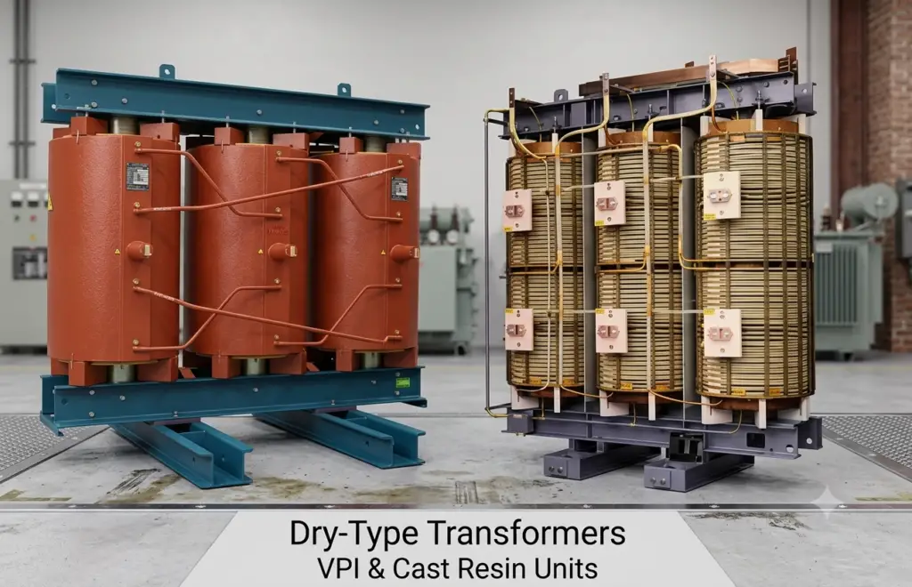
Because of their safe and environmentally friendly design, dry-type transformers are widely installed in indoor locations such as commercial buildings, hospitals, shopping malls, schools, offices, and other public facilities where fire risk must be minimized.
17. Two-Winding Transformer
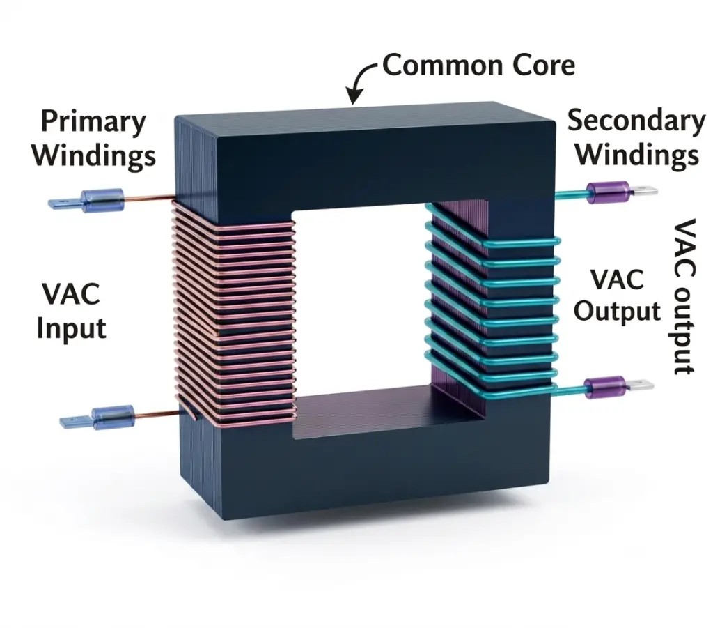
A two-winding transformer consists of two separate windings for each phase: a primary winding and a secondary winding. The primary winding receives the AC supply, while the secondary winding delivers power to the connected load.
Although the two windings are electrically isolated, they are magnetically linked through a common magnetic core. When alternating current flows through the primary winding, it creates a changing magnetic flux in the core. This varying flux induces an EMF in the secondary winding by the principle of mutual induction.
The secondary voltage depends on the turns ratio between the primary and secondary windings. Therefore, a two-winding transformer can either step up or step down the input voltage, depending on its design.
18. Auto Transformer
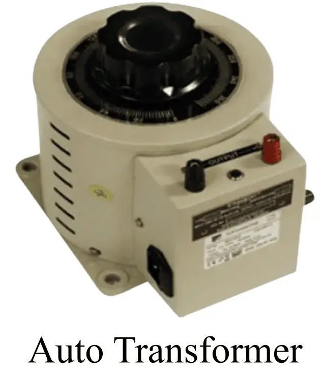
An electrical transformer that has only winding that serves as both primary and secondary winding is called an autotransformer. The autotransformer has tapping points on its winding to obtain a variable output voltage from a single input voltage.
Since the autotransformer has only one winding, it transmits power both electrically and magnetically from the primary to the secondary side. The same winding is shared between input and output, with different tapping points used for voltage variation.
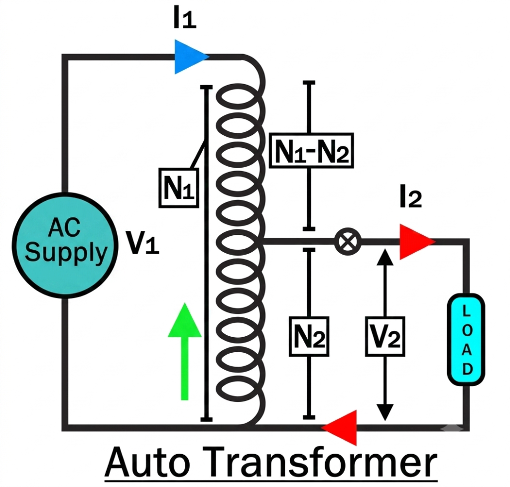
Autotransformers are smaller, lighter, and more cost-effective compared to conventional two-winding transformers. However, the main disadvantage is that they do not provide electrical isolation between primary and secondary circuits.
They also offer lower leakage reactance, lower losses, reduced excitation current, and higher VA rating for a given size and weight.
Autotransformers are commonly used in laboratories, induction motor starting, voltage regulation, and testing equipment.
19. Grounding (Earthing) Transformer
A grounding or earthing transformer is a special type of transformer used in three-phase power systems to create a neutral point when one is not naturally available. It provides a reference ground connection, helping to stabilize the system and control voltage during fault conditions.
In many power networks, especially those using delta-connected systems, there is no direct neutral point. A grounding transformer is installed to artificially establish this neutral, allowing the system to safely handle phase-to-earth faults. It also helps limit overvoltages and reduces voltage transients that may occur during ground faults.
These transformers are commonly used as part of the system grounding scheme and enable the flow of zero-sequence currents during fault conditions, improving system protection and stability.
A widely used design is the zigzag winding transformer, where the winding configuration helps in effectively creating a neutral point and balancing unbalanced loads.
20. Pulse Transformer
The pulse transformer is used in various electronic circuits for pulse generation in an isolated environment. The transformer is PCB mounted and it generates a constant magnitude pulse.

The pulse transformers provide isolation between the primary and secondary and output isolated pulse for digital logic gates or drivers.
Conclusion
The different types of transformers are designed to meet a wide range of electrical and industrial requirements. They can be classified based on voltage conversion, core construction, application, insulation and cooling method, phase, core material, and winding configuration. Understanding the different types of transformers and their applications helps engineers and technicians select the most suitable transformer for power generation, transmission, distribution, industrial equipment, and electronic devices. Choosing the right transformer improves system efficiency, reliability, safety, and long-term performance.
Read Next: