An auto transformer (or autotransformer) is a special type of electrical transformer with only one winding, used to step up or step down the voltage. In this article, we explain the auto transformer definition, circuit diagram, working principle, copper saving, advantages, and disadvantages—making it easy for students and professionals to understand.
What is an Auto transformer?
An autotransformer is an electrical machine that contains only one winding and is used to transform or change the level of voltage or current in an electrical system or circuit.
It is named an autotransformer because it consists of only one winding acting as the primary and secondary windings.
The function of an autotransformer is similar to a two-winding transformer. The only difference is that it has only one winding serving as primary and secondary.
Therefore, an auto transformer transforms electrical energy both electrically and magnetically.
Let us now discuss the working principle of autotransformers to understand how it works.
Auto Transformer Circuit Diagram and Working
Auto Transformer Diagram
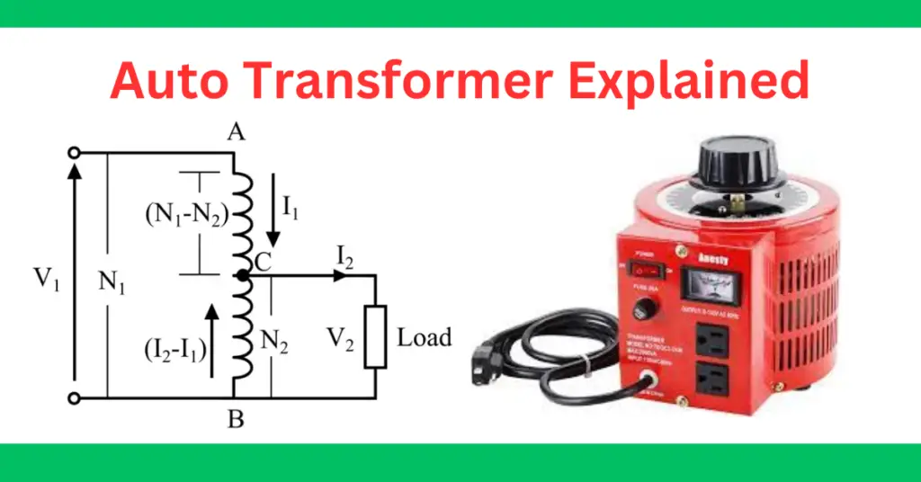
A circuit diagram of a typical autotransformer is depicted in the following figure.
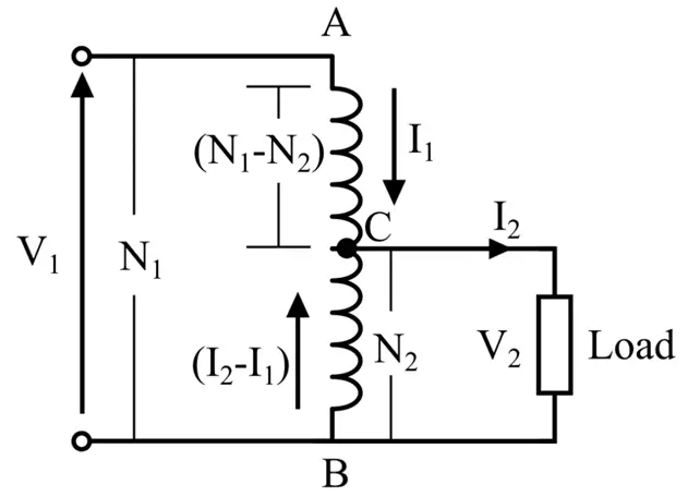
It can be seen in the diagram that it consists of only one winding acting as the primary and secondary. The winding is taped at different points to get the secondary winding terminals.
Auto Transformer Working Principle
In the above diagram, the winding AB has N1 turns and acts as the primary winding. The winding BC has N2 turns acting as the secondary winding.
The primary winding AB has a tapping at C, and part of the winding BC acts as a secondary winding. The input supply voltage is connected across the winding AB, and the load is connected across the winding BC. The tapping may be fixed or variable. When an AC voltage V1 is applied across AB, an alternating flux is generated in the core, inducing an emf E1 in the winding AB. A part of this induced EMF is transferred to the secondary circuit.
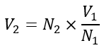
Let us consider V1 as the primary winding voltage and V2 as the secondary winding voltage.
Since the number of turns in the secondary winding is N2. Hence, the voltage available across the secondary winding will be,
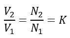
Therefore, the transformation ratio or turns ratio (K) of the auto transformer will be,
Since the secondary ampere-turns are opposite to primary ampere-turns, the current I2 is in phase opposition to I1. This means that the secondary voltage is lower than the primary one, and as a result, the current I2 is greater than I1. Therefore, the total current flowing through section BC is equal to the current (I2 – I1).
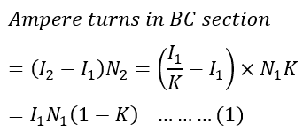
Ampere turns in section BC are equal to the current flowing in the BC section and the number of turns.
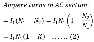
Ampere turns in section AC are equal to the current flowing in the BC section and the number of turns.
From equations (1) and (2), it is clear that ampere-turns of section BC and AC of auto transformer are equal, which is characteristic of the transformer action.
As we know, the autotransformer has only one winding. Therefore, there is a certain amount of copper saving in the autotransformer compared to a two-winding transformer for the same kVA rating.
Let us derive the expression for the weight of copper saved in an autotransformer compared to a two-winding transformer.
Copper Saving in Autotransformer
In an electrical transformer, the weight of copper required for constructing windings depends on the length and cross-sectional area of the winding.
As we know, the length of the winding is directly proportional to its number of turns. The cross-sectional area varies with the rated current of the winding.
Therefore, the weight of copper required in the winding is directly proportional to the product of number of turns in the winding and the rated current.
Hence, the weight of copper required for the part AC of the winding is directly proportional to (N1 – N2)I1.
The weight of copper required for the part BC is proportional to (I2 – I1)N2.
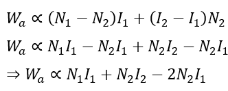
Thus, the total weight of copper required for making the winding of an autotransformer is directly proportional to (N1 – N2)I1 + (I2 – I1)N2.
It can be written as,
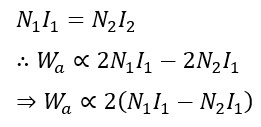
As we know, for a transformer,
Similarly, the weight of copper required for two winding transformers is directly proportional to
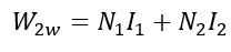
Since,
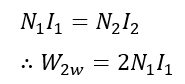
On comparing the two weights, we get,
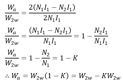
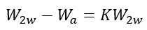
Thus, the saving of copper in an autotransformer as compared to a two-winding transformer is,
Advantages of Auto Transformer
The following are some key benefits of an autotransformer over a normal two-winding transformer:
- Smaller Size – For the same rating, an autotransformer has approximately half the size of a typical two-winding transformer.
- Less Manufacturing Cost – An autotransformer requires less manufacturing material, resulting in appreciable cost savings.
- Reduced Core and Copper Losses – An autotransformer has fewer core losses and copper losses due to reduced iron and copper material.
- Higher Efficiency – An autotransformer can transform electrical energy through electrical and magnetic conductions. Hence, it is more efficient than a two-winding transformer that relies only on magnetic conduction.
- Better Voltage Regulation – An autotransformer has better voltage regulation. It is because it has less voltage drop as there is only a single winding causing resistance and reactance.
- Variable Voltage – The output voltage of an autotransformer can be adjusted by changing the taping on the winding.
Disadvantages of Autotransformer
An autotransformer has several advantages. However, it also has various disadvantages listed below:
- High Insulation Required – Due to common primary and secondary windings, the low-voltage winding is also subjected to high voltage due to electrical conductivity betwween primary and secondary windings. Hence, to avoid breakdown in the low voltage winding, it has to provide insulation to withstand higher voltage.
- No Electrical Isolation between Primary and Secondary –Since an autotransformer uses a single winding for both the primary and secondary, it does not provide electrical isolation. Consequently, a fault or insulation failure can expose the secondary circuit to the high primary voltage, creating safety and equipment protection concerns.
- High-Fault Current –During a short-circuit fault, the load is connected directly to the power supply. Since the leakage reactance of the transformer is very low, it offers little opposition to the fault current. As a result, an extremely high current flows, which can damage electrical equipment if not interrupted by protective devices.
- Full Supply Voltage at Output under Open Circuit Fault Condition – In an autotransformer, if there is an open circuit fault in the common part of the winding, the full supply voltage will appear across the load.
Applications of Auto Transformer
The main applications of an autotransformer are given below:
- Autotransformers are used in testing labs to test repaired electrical devices.
- They are used in transmission and distribution lines to compensate for the line voltage drop.
- They are used for temperature adjustment in resistance heating.
- An autotransformer is also used to start and control the speed induction motors.
- Autotransformer is used as the main component in a voltage stabilizer.
Conclusion
An auto transformer is a compact and efficient electrical transformer that uses a single winding to adjust voltage levels. It is valued for saving copper, reducing size, and improving efficiency, though it lacks full electrical isolation and can carry high fault currents.
By understanding its diagram, working principle, benefits, drawbacks, and practical applications, students and professionals can effectively use auto transformers in power distribution, motor control, and voltage regulation. Mastering these concepts ensures better design choices and safer operation in electrical systems.
Related Articles: