Logic gates are the fundamental building blocks of every digital electronic system. Whether it is a computer, smartphone, calculator, microcontroller, PLC, or industrial automation system, every digital circuit is built using different combinations of logic gates.
In this comprehensive guide, you’ll learn everything about logic gates, including their working principle, symbols, truth tables, Boolean expressions, types, characteristics, applications, advantages, disadvantages, and much more.
What is a Logic Gate?
A logic gate is an electronic circuit that processes one or more binary inputs and produces a single binary output based on a predefined logical rule. Since digital systems operate using only two binary states—0 (LOW) and 1 (HIGH)—logic gates follow the principles of Boolean algebra to determine the output.
Logic gates are the fundamental building blocks of digital electronics. Each gate is designed to perform a specific function, such as AND, OR, NOT, NAND, NOR, XOR, or XNOR. By combining multiple logic gates, engineers can create complex digital circuits used in microprocessors, memory devices, computers, smartphones, industrial controllers, and many other electronic systems.
Key Characteristics of Logic Gates
Logic gates share several important characteristics that make them essential components of digital electronic systems:
- Operate on binary values: Logic gates accept inputs and produce outputs using only two logic levels—0 (LOW) and 1 (HIGH).
- Based on Boolean algebra: Every logic gate follows Boolean algebra rules to perform logical operations and generate the correct output.
- Perform specific logical functions: Each gate is designed for a particular operation, such as AND, OR, NOT, NAND, NOR, XOR, or XNOR.
- Can have one or multiple inputs: Depending on the gate type, a logic gate may have a single input (such as a NOT gate) or two or more inputs (such as AND and OR gates).
- Produce a single output: After processing the input signals, a logic gate generates one binary output that represents the result of the logical operation.
- Can be combined to form complex circuits: Individual logic gates are interconnected to build digital circuits such as flip-flops, multiplexers, adders, counters, registers, memory units, and microprocessors.
- Available as integrated circuits (ICs): In practical applications, logic gates are manufactured as integrated circuits using technologies such as TTL and CMOS, allowing millions of gates to be integrated onto a single chip.
- Used in almost every digital device: Logic gates are found in computers, smartphones, industrial controllers, communication equipment, consumer electronics, automotive systems, and many other digital devices.
How Logic Gates Work?
Logic gates work by processing one or more binary input signals according to the rules of Boolean algebra to produce a single binary output. Each input can exist in one of two logic states: 0 (LOW or False) or 1 (HIGH or True). Based on the combination of these input values, the logic gate performs its predefined logical operation and generates the corresponding output.
Every type of logic gate has its own logical function. For example, an AND gate produces a HIGH output only when all inputs are HIGH, whereas an OR gate produces a HIGH output if at least one input is HIGH. Similarly, a NOT gate inverts the input signal, while NAND, NOR, XOR, and XNOR gates perform their respective logical operations.
The relationship between the input combinations and the resulting output is represented using a truth table. A truth table lists every possible input combination and the corresponding output for a particular logic gate, making it an essential tool for analyzing and designing digital circuits.
In practical electronic systems, logic gates are implemented using semiconductor devices such as transistors. Millions or even billions of these transistors are integrated onto a single chip to build complex digital circuits, including processors, memory devices, microcontrollers, and communication systems.
Types of Logic Gates
Logic gates are classified into different types based on the logical operation they perform. Each gate is designed to process one or more binary input signals and produce a binary output according to a specific Boolean function. Together, these gates form the foundation of digital circuit design and are used to build everything from simple switching circuits to advanced microprocessors.
The seven commonly used logic gates are AND, OR, NOT, NAND, NOR, XOR, and XNOR. These gates can be grouped into three categories based on their functionality:
Basic Logic Gates
The AND, OR, and NOT gates are known as the basic logic gates because they perform the fundamental logical operations used in digital electronics. These gates serve as the building blocks for designing more complex logic circuits.
Universal Logic Gates
The NAND and NOR gates are called universal logic gates because either one can be used to implement all other logic gates. Due to their versatility, they are widely used in the design and fabrication of digital integrated circuits.
Exclusive Logic Gates
The XOR (Exclusive OR) and XNOR (Exclusive NOR) gates are known as exclusive logic gates. They are commonly used in arithmetic circuits, digital comparators, parity generators, error detection systems, and data processing applications where input comparison is required.
The following sections explain the working principle, Boolean expression, truth table, characteristics, and applications of each type of logic gate.
AND Gate
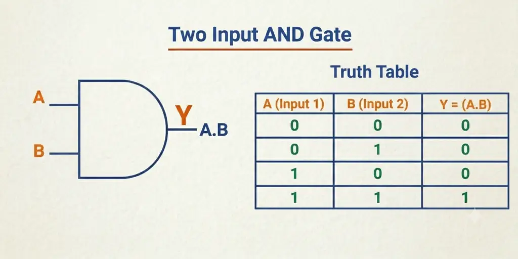
An AND gate is one of the three fundamental logic gates used in digital electronics. It performs the logical AND operation, also known as logical multiplication. The output of an AND gate becomes HIGH (1) only when all of its input signals are HIGH (1). If any input is LOW (0), the output remains LOW.
The Boolean expression of a two-input AND gate is:
This gate is widely used in digital systems where multiple conditions must be satisfied before an action is performed. Common applications include enable circuits, safety interlocks, permission logic, industrial control systems, and arithmetic circuits.
Truth Table
The figure below shows the symbol and truth table of the AND gate.
Key Characteristics
- Performs logical multiplication.
- Can have two or more input terminals.
- Produces HIGH output only when every input is HIGH.
- Commonly used for condition checking and control logic.
OR Gate
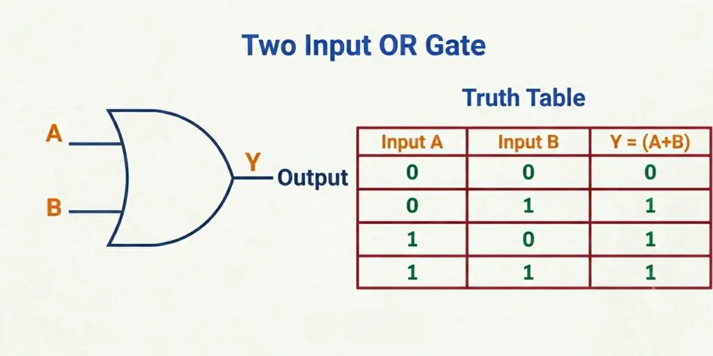
An OR gate is one of the three basic logic gates used in digital electronics. It performs the logical OR operation, also known as logical addition. The output of an OR gate becomes HIGH (1) when at least one of its input signals is HIGH (1). The output becomes LOW (0) only when all input signals are LOW (0).
The Boolean expression of a two-input OR gate is:
OR gates are widely used in digital circuits where multiple conditions can independently trigger an output. They are commonly found in alarm systems, control circuits, automation systems, decision-making logic, and signal-processing applications.
Truth Table
The figure below shows the symbol and truth table of the OR gate.
Key Characteristics
- Performs logical addition.
- Can have two or more input terminals.
- Produces a HIGH output when one or more inputs are HIGH.
- Generates a LOW output only when all inputs are LOW.
- Commonly used in decision-making and control logic circuits.
NOT Gate
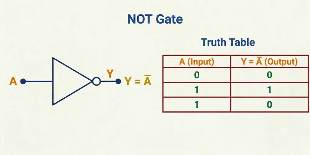
A NOT gate is one of the three basic logic gates used in digital electronics. Also known as an inverter, it performs the logical NOT operation by reversing the input signal. Unlike other basic logic gates, a NOT gate has only one input and one output. When the input is HIGH (1), the output becomes LOW (0), and when the input is LOW (0), the output becomes HIGH (1).
The Boolean expression of a NOT gate is:
Y = A’ or Y = Ā
NOT gates are widely used in digital circuits where signal inversion or complementing is required. They are commonly found in control circuits, digital memory, arithmetic logic units (ALUs), microprocessors, and other electronic systems that require opposite logic states.
Truth Table
The figure below shows the symbol and truth table of the NOT gate.
Key Characteristics
- Performs the logical NOT operation (inversion).
- Has one input terminal and one output terminal.
- Produces the complement of the input signal.
- Converts HIGH (1) to LOW (0) and LOW (0) to HIGH (1).
- Widely used for signal inversion and digital control applications.
NAND Gate
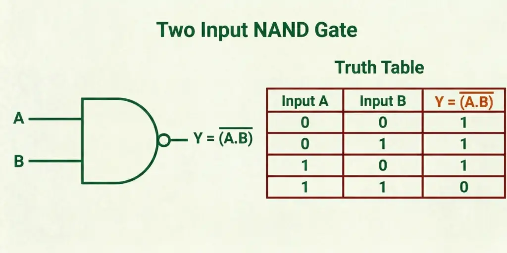
A NAND gate is a universal logic gate that performs the logical NAND operation, which is the complement of the AND operation. It is formed by combining an AND gate with a NOT gate. The output of a NAND gate becomes LOW (0) only when all of its input signals are HIGH (1). If any input is LOW (0), the output becomes HIGH (1).
The Boolean expression of a two-input NAND gate is:
Y = (A · B)’
Since a NAND gate is a universal gate, it can be used to implement all other logic gates, making it one of the most important gates in digital electronics. NAND gates are widely used in digital integrated circuits, arithmetic logic units (ALUs), memory circuits, microprocessors, control systems, and various combinational and sequential logic circuits.
Truth Table
The figure below shows the symbol and truth table of the NAND gate.
Key Characteristics
- Performs the complement of the AND operation.
- Can have two or more input terminals.
- Produces a LOW output only when all inputs are HIGH.
- Known as a universal logic gate because it can implement any other logic gate.
- Widely used in digital ICs, processors, memory circuits, and control logic.
NOR Gate
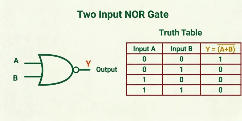
A NOR gate is a universal logic gate that performs the logical NOR operation, which is the complement of the OR operation. It is formed by combining an OR gate with a NOT gate. The output of a NOR gate becomes HIGH (1) only when all of its input signals are LOW (0). If any input is HIGH (1), the output becomes LOW (0).
The Boolean expression of a two-input NOR gate is:
Y = (A + B)’
Because a NOR gate is a universal gate, it can be used to implement all other basic and derived logic gates. NOR gates are widely used in digital circuit design, memory devices, latches, control systems, and various combinational and sequential logic circuits.
Truth Table
The figure below shows the symbol and truth table of the NOR gate.
Key Characteristics
- Performs the complement of the OR operation.
- Can have two or more input terminals.
- Produces a HIGH output only when all inputs are LOW.
- Known as a universal logic gate because it can implement any other logic gate.
- Commonly used in memory circuits, latches, and digital control systems.
XOR Gate
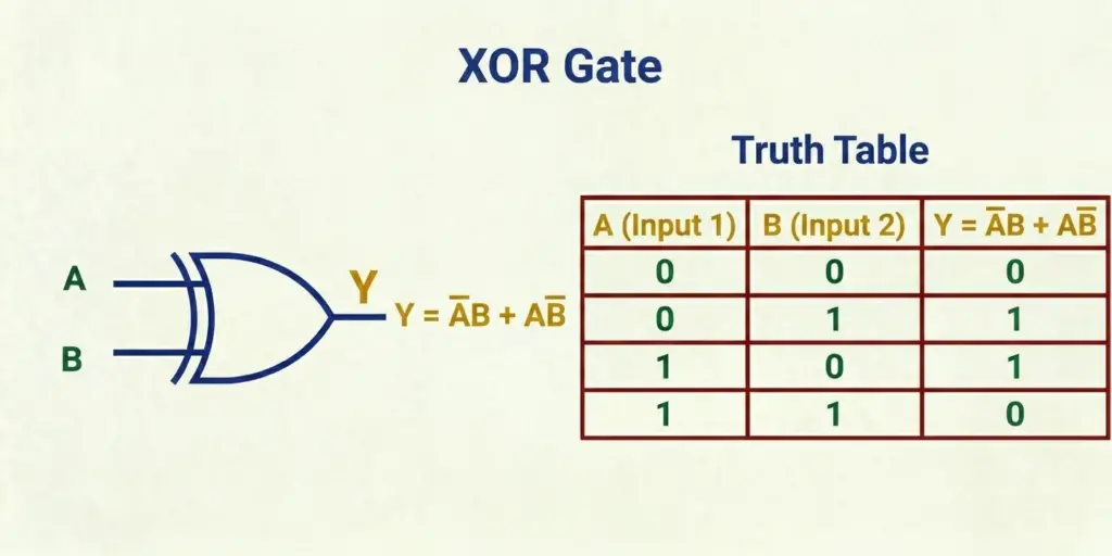
An XOR (Exclusive OR) gate is a special logic gate that performs the exclusive OR operation. Unlike an OR gate, the output of an XOR gate becomes HIGH (1) only when its input signals are different. If both inputs are the same (either both LOW or both HIGH), the output becomes LOW (0).
The Boolean expression of a two-input XOR gate is:
Y = A’B + AB’
or
Y = A ⊕ B
XOR gates are widely used in digital electronics for performing binary addition, parity generation, error detection, data encryption, and digital comparison. They are an essential component of half adders, full adders, arithmetic logic units (ALUs), and communication systems.
Truth Table
The figure below shows the symbol and truth table of the XOR gate.
Key Characteristics
- Performs the exclusive OR operation.
- Produces a HIGH output only when the input signals are different.
- Typically has two input terminals and one output terminal.
- Commonly used in arithmetic circuits, parity checkers, and error detection systems.
- Plays an important role in digital communication and data processing applications.
XNOR Gate
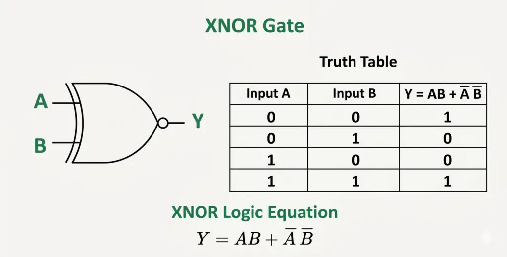
An XNOR (Exclusive NOR) gate is a special logic gate that performs the complement of the XOR operation. It is formed by combining an XOR gate with a NOT gate. The output of an XNOR gate becomes HIGH (1) only when both input signals are the same, that is, when both inputs are LOW (0) or both are HIGH (1). If the inputs are different, the output becomes LOW (0). Because it detects whether two binary values are equal, the XNOR gate is also known as the equivalence gate.
The Boolean expression of a two-input XNOR gate is:
Y = AB + A’B’
or equivalently,
Y = (A ⊕ B)’
XNOR gates are widely used in digital comparators, equality detectors, parity checking circuits, error detection systems, digital communication, and other applications where comparing two binary inputs is required.
Truth Table
The figure below shows the symbol and truth table of the XNOR gate.
Key Characteristics
- Performs the complement of the XOR operation.
- Produces a HIGH output only when both input signals are identical.
- Typically has two input terminals and one output terminal.
- Also known as the equivalence gate because it detects equal inputs.
- Commonly used in digital comparators, parity checkers, and equality detection circuits.
Logic Gates Comparison
Although each logic gate performs a unique logical operation, comparing them side by side makes it easier to understand their differences. The table below summarizes the seven commonly used logic gates based on the logical operation they perform and the condition under which their output becomes HIGH (1). Use it as a quick reference to review the key characteristics of each logic gate.
| Logic Gate | Logical Operation | Output is HIGH (1) When |
| AND | Logical Multiplication | All inputs are HIGH |
| OR | Logical Addition | At least one input is HIGH |
| NOT | Logical Inversion | The input is LOW |
| NAND | Complement of AND | At least one input is LOW |
| NOR | Complement of OR | All inputs are LOW |
| XOR | Exclusive OR | The inputs are different |
| XNOR | Complement of XOR (Exclusive NOR) | The inputs are the same |
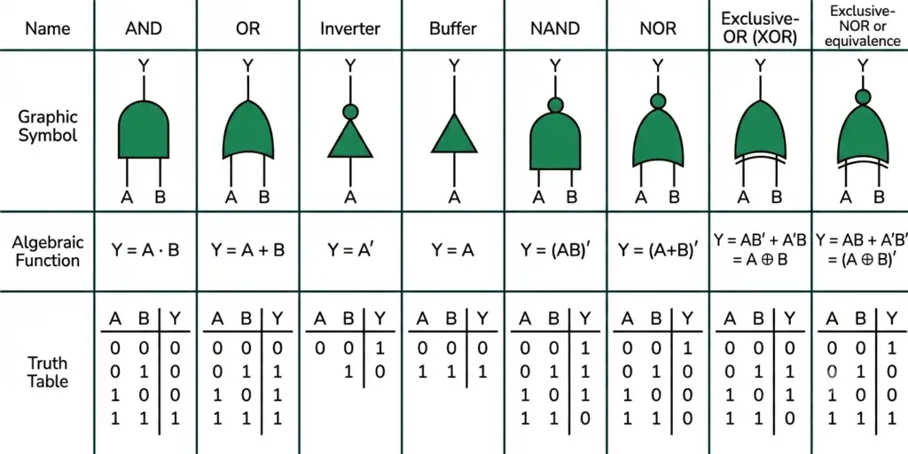
Summary: Logic Gates with Symbols, Boolean Expressions, and Truth Tables
The illustration below summarizes the symbols, Boolean expressions, and truth tables of the seven basic and derived logic gates. Use it as a quick reference to compare the behavior and logical functions of each gate without reviewing their individual sections.
Applications of Logic Gates
Logic gates are the fundamental building blocks of digital electronics and are used in almost every digital system. By combining different logic gates, engineers can design circuits that perform arithmetic operations, process data, store information, and control electronic devices. From simple consumer gadgets to advanced industrial automation systems, logic gates play a vital role in modern technology.
Some of the major applications of logic gates include:
- Computers: Logic gates perform arithmetic operations, execute instructions, process data, and control the operation of computer processors.
- Microprocessors and Microcontrollers: They form essential components such as arithmetic logic units (ALUs), control units, registers, and memory interfaces, enabling processors to execute digital instructions.
- PLC and Industrial Automation: Logic gates are used to implement control logic, machine sequencing, safety interlocks, and automated manufacturing processes.
- Robotics: They help robots process sensor inputs, make logical decisions, and control motors and actuators for automated tasks.
- Digital Communication Systems: Logic gates are used for data encoding, decoding, switching, signal processing, and error detection during digital communication.
- Memory Devices: RAM, ROM, cache memory, and other storage devices rely on logic gates to store, retrieve, and manage binary data.
- Embedded Systems and Consumer Electronics: Smartphones, televisions, calculators, washing machines, smart home devices, and many other electronic products use logic gates to process digital information and control system functions.
- Medical and Security Equipment: Medical instruments, access control systems, alarm systems, and surveillance equipment use logic gates for signal processing, monitoring, and decision-making.
Advantages of Logic Gates
Logic gates offer several advantages that make them the foundation of modern digital electronics. Their ability to process binary data accurately and at high speed makes them suitable for a wide range of applications, from simple electronic circuits to advanced computing systems.
- High operating speed: Logic gates process binary signals within nanoseconds, enabling digital circuits to perform millions or even billions of operations every second.
- Reliable operation: They provide consistent and accurate outputs when operated within their specified voltage and operating conditions.
- Low power consumption: Modern CMOS logic gates consume very little power, making them ideal for battery-powered and portable electronic devices.
- Easy circuit design: Individual logic gates can be combined to design complex digital circuits such as adders, multiplexers, counters, and processors.
- Scalable architecture: Logic gates can be integrated in large numbers on a single chip, allowing the development of highly sophisticated digital systems.
- Compact size: Advances in integrated circuit technology enable millions or billions of logic gates to be fabricated on a single semiconductor chip.
- High accuracy: Logic gates operate using well-defined binary states, reducing ambiguity and improving the accuracy of digital signal processing.
- Foundation of digital electronics: Nearly every modern digital device, including computers, smartphones, embedded systems, and industrial controllers, is built using combinations of logic gates.
Limitations of Logic Gates
Although logic gates provide numerous advantages, they also have certain limitations that should be considered during the design of digital systems.
- Operate only with binary signals: Logic gates work with only two logic levels—LOW (0) and HIGH (1)—making them unsuitable for directly processing analog signals.
- Propagation delay: Every logic gate requires a small amount of time to respond to changes in its inputs, which can affect the performance of high-speed digital circuits.
- Susceptibility to noise: Electrical noise, voltage fluctuations, and electromagnetic interference can lead to incorrect switching if proper circuit design practices are not followed.
- Power supply dependency: Logic gates require a stable and regulated power supply to operate reliably. Variations in supply voltage may affect circuit performance.
- Design complexity: As digital systems become larger and more complex, designing, testing, and troubleshooting interconnected logic gate circuits becomes increasingly challenging.
Conclusion
Logic gates are the foundation of every digital electronic system. From simple switching circuits to advanced processors containing billions of transistors, every digital device relies on combinations of logic gates to perform logical operations.
Whether you’re a student learning digital electronics or an engineer designing complex digital systems, understanding logic gates is essential because they form the foundation of modern computing, embedded systems, communication devices, and industrial automation. Mastering the seven basic logic gates provides the knowledge required to analyze, design, and troubleshoot digital circuits effectively.
Frequently Asked Questions (FAQs)
Logic gates are electronic circuits that perform logical operations on binary inputs to produce a binary output.
There are three basic logic gates: AND, OR , & NOT gate
NAND and NOR gates are universal logic gates.
The AND gate performs logical multiplication.
The NOT gate is called an inverter because it reverses the input signal.
Because it produces HIGH output only when the inputs are different.
Read Next:
- XNOR Gate: Symbol and Truth Table
- NOT Gate: Logic Symbol and Truth Table
- Exclusive-OR Gate with EX-OR Gate Truth Table
- Universal Logic Gate: NAND Gate and NOR Gate
- NAND Gate- Symbol, Truth Table, Circuit Diagram, Working
- AND Gate: Symbol, Truth Table, Working, Circuit Diagram
- OR Gate: Symbol, Truth Table, Working, Types & IC Numbers
- NOR Gate- Symbol, Truth Table and Circuit Diagram