Binary Adder in a digital circuit does the arithmetic sum of two binary numbers supported with any length. The binary adder is implemented using logic gates, such as XOR Gate and AND Gate.
In digital electronics, binary numbers are used to represent data and information. Therefore, we have to perform all the arithmetic operations on the binary numbers using digital electronic systems. A binary adder is a digital circuit that can perform the addition of two or more binary numbers.
This article describes binary adder circuits, their types, logic circuit diagram, truth table, and applications. So, let’s begin with the basic definition of binary adder.
What is a Binary Adder?
A binary adder is a digital logic circuit that is used to perform the arithmetic sum of two binary numbers. A binary adder is implemented by combining logic gates in a proper manner.
Binary adder performs the addition operation on two binary numbers as per the following four rules:
- 0 + 0 = 0
- 0 + 1 = 1
- 1 + 0 = 1
- 1 + 1 = 0 and carry = 1
A binary adder is one of the most important logic circuits in any digital system like a computer, calculator, microcontroller, and more.
Types of Binary Adders
Binary adders can be classified into the following two main types depending on the number of bits (binary digits) that they can add:
- Half Adder
- Full Adder
Let us now discuss each type of binary adder in detail.
What is a Half Adder?
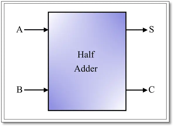
A half adder is a type of binary adder that is capable of adding only two binary digits (bits). Therefore, a half adder accepts only two input bits and gives two outputs, one is the sum bit and another is the carry output bit. The block diagram of a half adder is shown in the following figure.
We can design a half adder using an XOR gate and an AND gate as shown in the following figure.
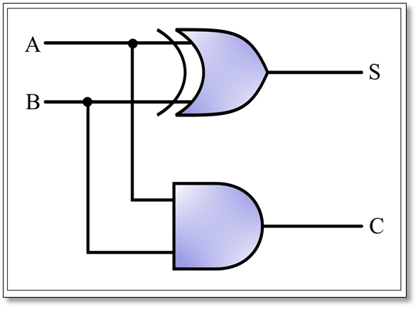
In this logic circuit diagram of the half adder, A and B are the input bits and S and C are the output sum and output carry bits respectively.
In the case of a half adder, the carry generated is not forwarded to the next addition and hence it is named so.
Truth Table of Half Adder
The following table is the truth table of a half adder and it gives information about the operation of the half-adder circuit:
| Inputs | Outputs | ||
| A | B | Sum (S) | Carry (C) |
| 0 | 0 | 0 | 0 |
| 0 | 1 | 1 | 0 |
| 1 | 0 | 1 | 0 |
| 1 | 1 | 0 | 1 |
Boolean Expression of Half Adder
We can obtain the Boolean function of half adder directly from its truth table. The Boolean functions for sum and carry outputs of a half adder are given below.
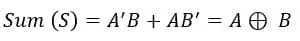
The Boolean function for the sum (S) output of the half adder is given by,
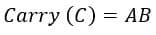
The Boolean function for carry (C) output of the half adder is given by,
What is a Full Adder?
In digital electronics, a full adder is another type of binary adder used to perform the addition of binary digits. Full adder overcomes the issues associated with the half adder, as it can forward the carry output to the next addition.
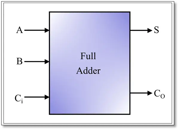
Therefore, a full adder has three input lines namely, two binary digits and a carry input from the previous addition, and two output lines namely sum and carry output. The block diagram of a full adder is depicted in the following figure.
The logic circuit of a full adder can be realized using an XOR gate, three AND gates, and an OR gate. The following figure shows the connection diagram of a full adder.
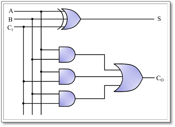
In this logic circuit diagram of the full adder, A, B, and Ci are the input bits to the adder circuit, and S and Co are the output bits.
Truth Table of Full Adder
The following table is the truth table of the full adder and it provides information about the operation of full adder circuit for different input combinations:
| Inputs | Outputs | |||
| A | B | Ci | Sum (S) | Carry (Co) |
| 0 | 0 | 0 | 0 | 0 |
| 0 | 0 | 1 | 1 | 0 |
| 0 | 1 | 0 | 1 | 0 |
| 0 | 1 | 1 | 0 | 1 |
| 1 | 0 | 0 | 1 | 0 |
| 1 | 0 | 1 | 0 | 1 |
| 1 | 1 | 0 | 0 | 1 |
| 1 | 1 | 1 | 1 | 1 |
Boolean Expression of Binary Full Adder
Boolean expression is a logic function of the adder circuit which mathematically represents the operation of the circuit. We can directly obtain the Boolean functions for sum (S) and carry output (Co) of the full adder as described below.
The Boolean function for the sum (S) output of the full adder is given by,

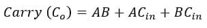
The Boolean function for carry (Co) output of the full adder is given by,
Advantages of Binary Full Adder over Half Adder
The major benefits of a full adder over half adder are listed below:
- It can perform complete addition, as it is capable to add carry from previous addition as well.
- It can perform binary subtraction.
- It can be used to implement various complex arithmetic circuits like parallel adder, multiplexers, and more.
- It performs binary addition at a relatively higher speed.
Applications of Binary Adder
The main applications of binary adders are listed below:
- In the arithmetic logic unit (ALU) of microprocessors.
- To implement full adder circuits.
- In digital calculators.
- Used in microcontrollers to calculate addresses.
- They are also used in graphical processing unit in computers.
- Binary adders are also used in performing binary subtraction and multiplication.
In conclusion, a binary adder is an important digital circuit used to perform various arithmetic operations like addition, subtraction, multiplications, etc. on binary digits. Binary adders play a vital role in digital electronics systems.