Nand Gate and NOR Gate are universal logic gates. In this article, we will discuss universal logic gates in digital electronics and the implementation of basic logic gates (AND, OR, and NOT) using universal logic gates. So, let’s begin with the basic definition of the universal logic gate.
In digital electronics, the logic gates are classified into two major categories, namely, basic logic gates and universal logic gates. There are three basic logic gates, namely AND gate, OR gate, and NOT gate.
What is a Universal Gate?
In digital electronics, a universal logic gate is one that can be used to implement any logical function without using any other type of logic gate.
In digital electronics, there are two types of universal logic gates, namely, NAND gate and NOR gate. These are called universal logic gates because they can perform all three basic logic operations, i.e., AND, OR, and NOT. Therefore, we can realize any logical function using only NAND gates or only NOR gates.
Let us now discuss the NAND gate and NOR gate in detail.
What is Universal NAND Gate?
A NAND gate is a universal logic gate used in digital electronic systems to implement logical functions.
The NAND gate can have two or more inputs and only one output. It is basically a combination of two basic logical functions, namely, AND and NOT, i.e.
NAND Gate = AND Gate + NOT Gate
Hence, it is also called NOTed AND gate.
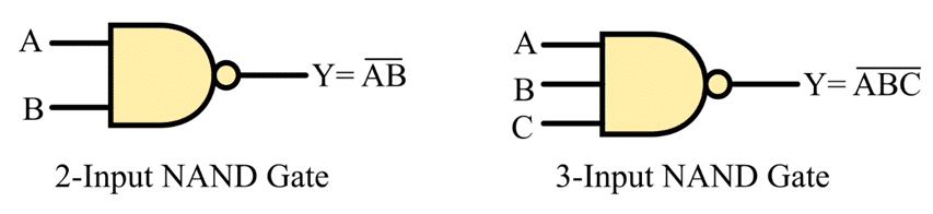
The logic circuit symbols of two input and three input NAND gates are depicted in the following figure.
Truth Table of NAND Gate
The table that describes the relationship between input variables and output variables of a logic gate is referred to as a truth table.
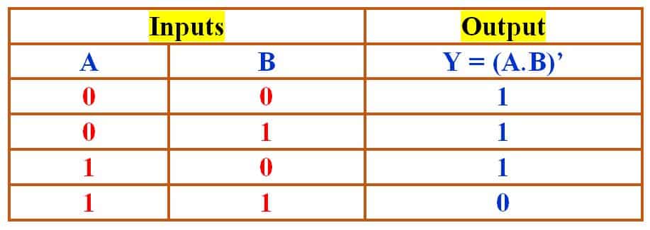
The following is the truth table of a two-input NAND gate.
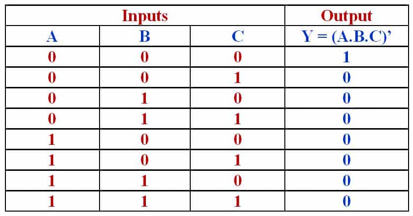
The following is the truth table of a three-input NAND gate.
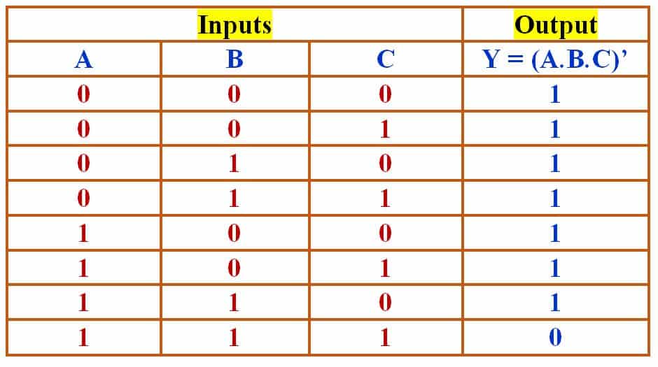
From the above truth tables, it is clear that if any of the inputs of the NAND gate is low (logic 0), the output will be high (logic 1), and if all the inputs of the NAND gate are high (logic 1), the output will be low (logic 0).
Boolean Expression of NAND Gate
The Boolean expression is a logic function that describes the behavior of a logic gate for different input combinations.
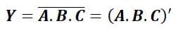
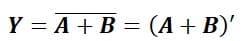
The Boolean expression of a two-input NAND gate is given below.
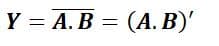
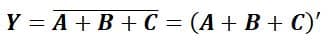
The Boolean expression of a three-input NAND gate is given below,
What is Universal NOR Gate?
A NOR gate is a universal logic gate used in digital electronic systems to implement logical functions.
The NOR gate can have two or more inputs and only one output. It is basically a combination of two basic logical functions, namely, OR and NOT, i.e.
NOR Gate = OR Gate + NOT Gate
Hence, it is also called the NOTedOR gate.
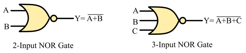
The logic circuit symbols of two-input and three-input NOR gates are depicted in the following figure.
Truth Table of Universal Logic NOR Gate
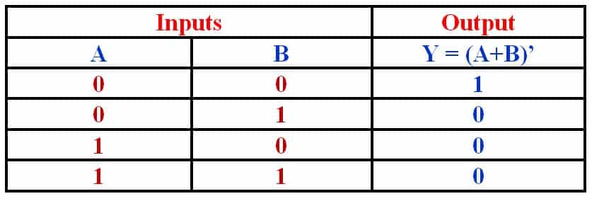
The following is the truth table of a two-input NOR gate:
The following is the truth table of a three-input NOR gate:
From the above truth tables, it is clear that if any of the inputs of the NOR gate is high (logic 1), the output will be low (logic 0), and if all the inputs of the NOR gate are low (logic 0), the output will be high (logic 1).
Boolean Expression of NOR Gate
The Boolean expression of a two-input NOR gate is given below.
The Boolean expression of a three-input NOR gate is given below.
After discussing the NAND and NOR gates individually, let us now discuss the implementation of basic logic gates (AND, OR, and NOT) using NAND and NOR gates.
Implementation of Basic Logic Gates using Universal Logic Gates
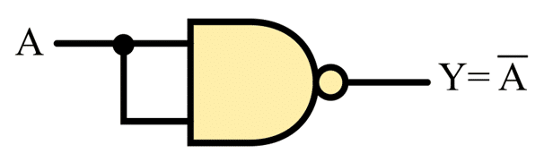
1. NOT Gate using NAND Gate
The following figure shows a NOT gate using a NAND gate.
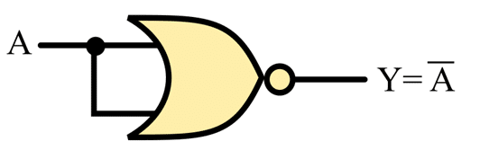
2. NOT Gate using NOR Gate
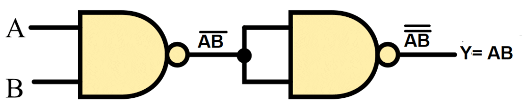
3. AND Gate using NAND Gate
The following figure shows an AND gate using a universal NAND gate.
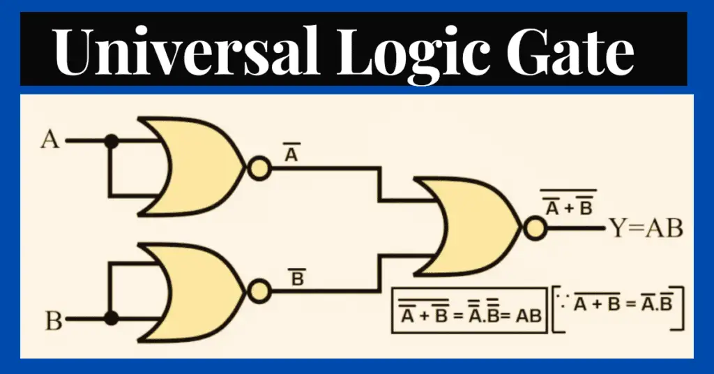
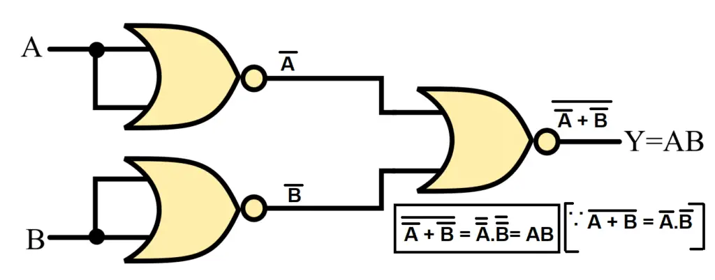
4. AND Gate using NOR Gate
The following figure shows an AND gate using a universal NOR gate.
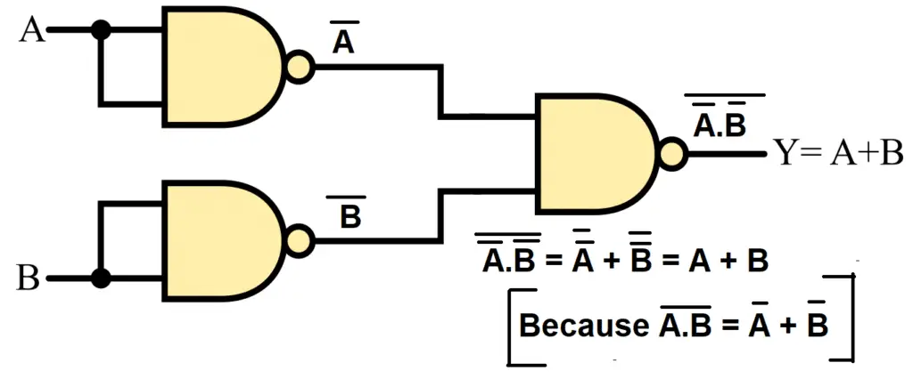
5. OR Gate using NAND Gate
The following figure shows an OR gate using a universal NAND gate.
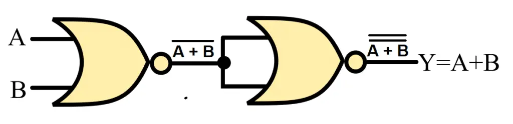
6. OR Gate using NOR Gate
The following figure shows an OR gate using NOR gate.
Conclusion
Hence, this is all about universal logic gates in digital electronics. From the above discussion, it is clear that we can implement all three basic logic functions, i.e., AND, OR, and NOT, using only NAND gates or only NOR gates. That is why NAND and NOR gates are referred to as universal logic gates.