In this article, we will discuss the logic NAND gate, its definition, truth table, Boolean expression, electrical equivalent circuit, and more. So, let’s get started with the basic definition of logic NAND gate.
What is NAND Gate?
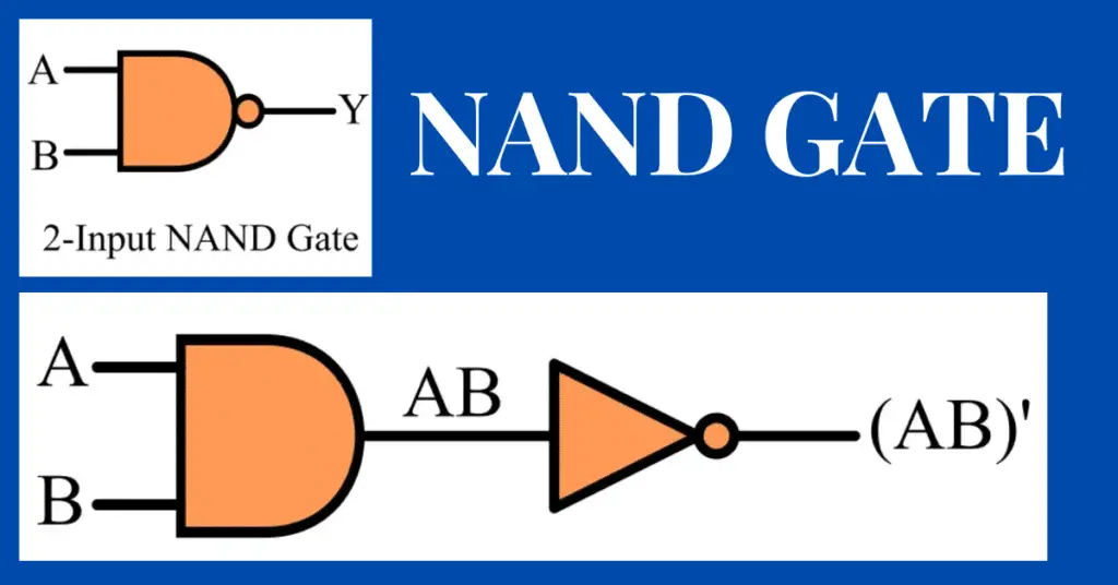
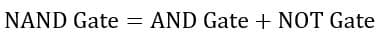
In digital electronics, a NAND gate is a type of universal logic gate using which one can implement any basic logic function. The NAND gate is basically a combination of two basic logic gates, i.e., AND and NOT, hence it is also called Noted AND gate.
The NAND gate performs the same operation as an AND gate followed by a NOT gate, i.e.
The NAND gate produces a low or logic 0 output, when all of its inputs are high or logic 1, and it produces a high or logic 1 output when any of its inputs is low or logic 0. Therefore, the NAND gate is an inversion of the AND gate in terms of operation.
Symbol of NAND Gate
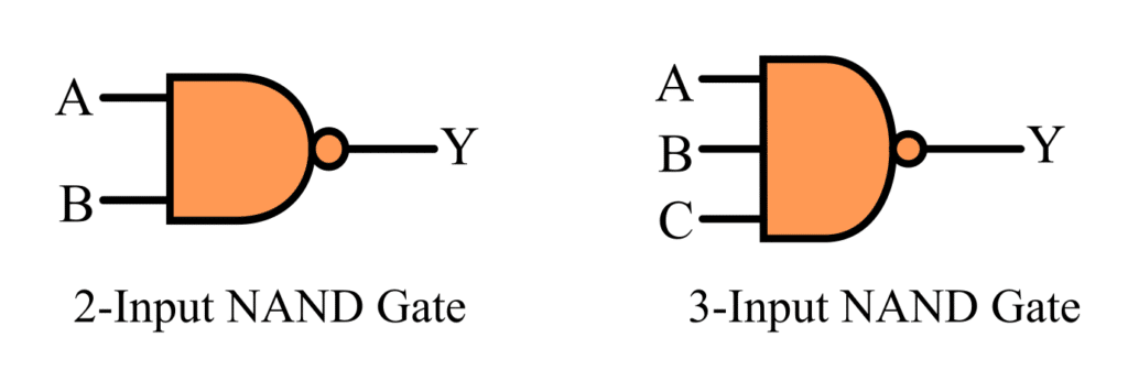
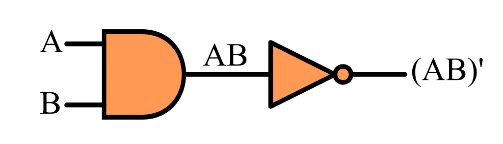
The basic logic symbol of the NAND gate is shown in the following figure.
Boolean Expression of NAND Gate
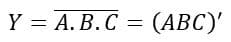
The Boolean expression of a two-input NAND gate is given below.
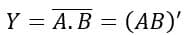
Where A and B are the input variables, and Y is the output variable of the given NAND gate.
The Boolean expression of a three-input NAND gate is given as follows:
Where, A, B, and C are the input variables, and Y is the output variable of the given NAND gate.
Working of NAND Gate
The operation of a two-input NAND gate for different possible combinations of inputs is as follows:
2-Input NAND Gate
- When A = 0 and B = 0, the output Y is 1.
- When A = 0 and B = 1, the output Y is 1.
- When A = 1 and B = 0, the output Y is 1.
- When A = 1 and B = 1, the output Y is 0.
3-Input NAND Gate
The operation of a three-input NAND gate for different possible combinations of inputs is described below:
- When A = 0, B = 0, and C = 0, the output Y is 1.
- When A = 0, B = 0, and C = 1, the output Y is 1.
- When A = 0, B = 1, and C = 0, the output Y is 1.
- When A = 0, B = 1, and C = 1, the output Y is 1.
- When A = 1, B = 0, and C = 0, the output Y is 1.
- When A = 1, B = 0, and C = 1, the output Y is 1.
- When A = 1, B = 1, and C = 0, the output Y is 1.
- When A = 1, B = 1, and C = 1, the output Y is 0.
Hence, from this discussion, it is clear that the output of the NAND gate is low only when all of its inputs are high, for the rest input combinations, the output is high.
Truth Table of NAND Gate
2-Input NAND Gate
The following is the truth table of a two-input NAND gate:
| Input | Output | |
| A | B | Y = (AB)’ |
| 0 | 0 | 1 |
| 0 | 1 | 1 |
| 1 | 0 | 1 |
| 1 | 1 | 0 |
3-Input NAND Gate
| Input | Output | ||
| A | B | C | Y = (AB)’ |
| 0 | 0 | 0 | 1 |
| 0 | 0 | 1 | 1 |
| 0 | 1 | 0 | 1 |
| 0 | 1 | 1 | 1 |
| 1 | 0 | 0 | 1 |
| 1 | 0 | 1 | 1 |
| 1 | 1 | 0 | 1 |
| 1 | 1 | 1 | 0 |
Realization of NAND Gate using Basic Logic Gates
As mentioned in the introductory section, the NAND gate is a combination of basic logic gates namely, AND gate and NOT gate.
Therefore, we can realize or implement a NAND gate by connecting an AND gate and a NOT gate as shown in the following figure.
Multi-Input NAND Gate
We can implement a higher order NAND gate, i.e. NAND gate having more number of inputs by using two-input NAND Gates.
For example, the realization of a six-input NAND Gate using six two-input NAND gates and a three-input NAND gate is depicted in the following figure.
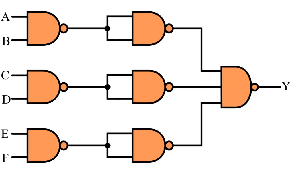
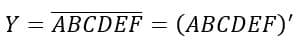
The output of this logic circuit is given as follows:
Realization of Basic Logic Gates using NAND Gate
As we mentioned above that, the NAND gate is a universal logic gate, hence we can implement any basic logic using this NAND gate.
1. AND Gate using NAND Gate
The implementation of an AND gate using a NAND gate is shown in the following figure.
The output of this logic circuit is equivalent to AND gate output, i.e.

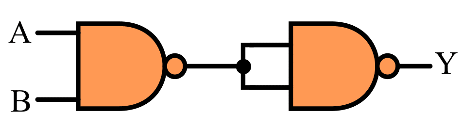
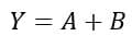
2. OR Gate using NAND Gate
The implementation of an OR Gate using NAND is shown in the following figure.
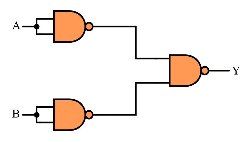
The output of this NAND logic circuit is equivalent to an OR gate output, i.e.
3. NOT Gate using NAND Gate
The implementation of a NOT gate using a NAND gate is shown in the following figure.
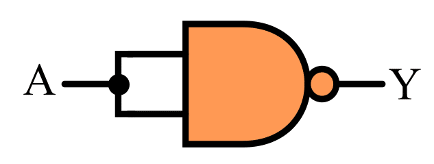
The output of this NAND logic circuit is equivalent to the NOT gate output, i.e.
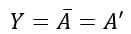
NAND Gate in RTL Logic
We can construct a NAND gate using RTL or Resistor Transistor Logic. The implementation of a two-input NAND gate in resistor transistor logic is shown in the following figure.
When both transistor T1 and T2 conducts we get low output( A=1, B=1, then Y=0). If any of the transistors is not conducting then we will get high output( A=1, B=0, then Y=1)
NAND Gate Integrated Circuits
NAND gates also come in the form of integrated circuits (ICs). The commonly used NAND gate ICs are listed in the following table.
| Logic Family | IC Name & Input |
| TTL (Transistor-Transistor Logic) Logic | 74LS00 (Quad 2-input) |
| TTL Logic | 74LS10 (Triple 3-input) |
| TTL Logic | 74LS20 (Dual 4-input) |
| TTL Logic | 74LS30 (Single 8-input) |
| CMOS (Complementary Metal Oxide Semiconductor) Logic | CD4011 (Quad 2-input) |
| CMOS Logic | CD4023 (Triple 3-input) |
| CMOS Logic | CD4012 (Dual 4-input) |
This is all about the NAND Gate, its definition, truth table, operation, Boolean expression, etc.