Definition: A Capacitive Voltage Transformer (CVT) is an electrical device that steps down high-voltage signals to a lower measurable voltage level. CVTs are commonly used in high-voltage transmission and distribution systems for metering and protection.
A Capacitive voltage transformer (CVT) is also known as a Capacitor Voltage Transformer, Capacitor Transformer, Capacitor Potential Transformer (CPT), Capacitor Divider Transformer, CVT transformer, or Voltage Capacitor Transformer These alternative names emphasize the use of capacitors in the voltage transformation process and their role in potential measurement and voltage stepping down.
What is the purpose of a CVT?
Capacitive Voltage Transformers (CVTs) are essential in electrical power systems for several reasons. Firstly, they enable the safe and accurate measurement of high voltages. This is important for monitoring and managing electricity usage, as well as for billing purposes.
Capacitive Voltage Transformer also plays a crucial role in protecting the power system. They provide the necessary voltage signals to protective relays, which detect and isolate faults, preventing damage to equipment and maintaining system stability.
In terms of cost efficiency, CVTs are more economical than traditional electromagnetic voltage transformers, especially for very high-voltage applications. They are also lighter and more compact, making them easier to transport, install, and maintain.
Another important use of CVTs is in power line carrier communication (PLCC). They allow communication signals to be transmitted over power lines, enabling remote monitoring, control, and protection of the power system.
CVTs are known for their reliability and accuracy. They provide a stable and precise voltage output under various operating conditions, which is crucial for metering and protection. Additionally, they enhance safety by stepping down high voltages to lower levels, providing electrical isolation for those working with the equipment.
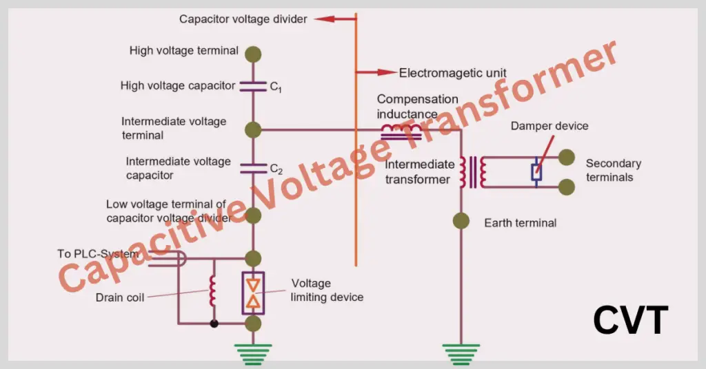
Main Parts of Capacitive Voltage Transformer
A CVT consists of a series of capacitors and an electromagnetic transformer. The primary components include:
- Capacitive Divider: This part of the CVT consists of a series of capacitors connected between the high-voltage line and the ground. The voltage across one of the capacitors (or a group of capacitors) is used as the input to the transformer.
- Intermediate Transformer: The reduced voltage from the capacitive divider is then fed into this transformer, which further steps down the voltage to a level suitable for measurement and relay protection.
- Compensating Reactor: This component corrects the phase angle and magnitude of the secondary voltage, ensuring accurate voltage measurement.
Capacitive Voltage Transformer Working
The CVT Diagram is shown below.
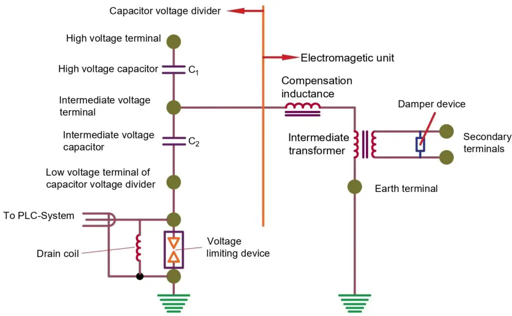
A Capacitive Voltage Transformer (CVT) works by using a combination of capacitors and a transformer to step down high voltages to a lower, more manageable level for measurement and protection. Here’s a step-by-step explanation of how a CVT works:
- High Voltage Input: The Capacitive Voltage Transformer(CVT) is connected to a high-voltage power line. The high voltage from this line is applied across a series of capacitors, which form a capacitive divider.
- Capacitive Divider: The capacitive divider consists of two or more capacitors connected in series. When high voltage is applied across this series of capacitors, the voltage is divided proportionally among them. This division reduces the high voltage to a lower intermediate voltage.
- Intermediate Voltage: The intermediate voltage is taken from the point between the capacitors in the divider. This reduced voltage is still too high for direct measurement but is significantly lower than the original high voltage.
- Step-Down Transformer: The intermediate voltage is then fed into an electromagnetic transformer. This transformer further steps down the voltage to a very low level suitable for standard measuring instruments and protective relays.
- Compensating Reactor: The CVT includes a compensating reactor to ensure accuracy. This reactor corrects any phase shift and adjusts the magnitude of the output voltage, ensuring that the voltage measurement is precise and accurate.
- Low Voltage Output: The final output from the step-down transformer is a low voltage that is an accurate representation of the high voltage in the power line. This low voltage can be safely used for metering and protective relays.
- Protective Relays and Meters: The low voltage output is then used by protective relays to monitor the system and isolate faults. It is also used by energy meters for accurate voltage measurement and energy billing.
In summary, a CVT works by first using a capacitive divider to reduce the high voltage to an intermediate level, then using a transformer to further step it down to a low, safe level for measurement and protection. The compensating reactor ensures that the output voltage is accurate, making CVTs essential for the reliable operation of high-voltage power systems.
Applications
- Metering: CVTs are used for accurate voltage measurement in high-voltage systems.
- Protection: They provide voltage signals for protective relays in power systems.
- Communication: CVTs can also be used to couple communication signals to power lines in Power Line Carrier Communication (PLCC) systems.
Advantages
- Cost-effective compared to traditional electromagnetic voltage transformers, especially for very high voltage applications.
- They are lighter and more compact, making them easier to install and maintain.
- It provides a stable and accurate voltage signal over a wide range of operating conditions.