In this article, we will learn about capacitive voltage divider. As we know, a voltage divider is a circuit that is used to provide multiple voltages from a single voltage. In other words, a voltage divider is an electrical circuit that is used to split or divide a single high voltage into multiple low voltages.
A voltage divider circuit can be designed by using different electric circuit components like resistors, inductors, and capacitors. In this article, we will discuss the design of a voltage divider circuit using capacitors, referred to as a capacitive voltage divider.
What is a Capacitive Voltage Divider?
A voltage divider is simply a series circuit. As we know, the circuit elements are joined in a chain form in a series circuit. When a voltage is applied across this series combination of elements, it will be distributed across all the elements based on their electronic properties, i.e., resistance or reactance.
A typical voltage divider circuit using two capacitors is depicted in the following figure.
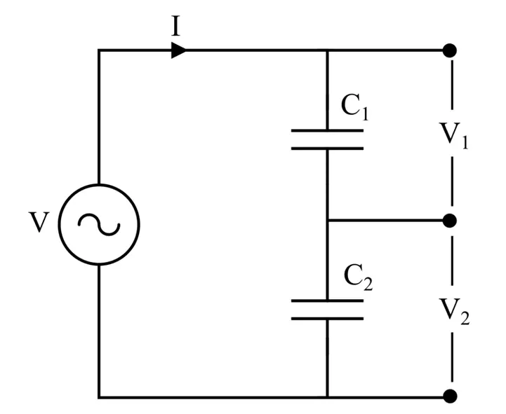
It consists of two capacitors, namely, C1 and C2, which are connected in series across a source voltage V. The current flowing through both capacitors is the same, as they are connected in series, and there is only one path for current flow.
Before proceeding further with the technical details of a capacitive voltage divider, let us first know some basics of a capacitor.
What is a Capacitor?
A capacitor is an electronic circuit component that stores electric charge in the form of electrostatic charge.
A capacitor typically consists of two metal plates that are separated by an insulating medium called a dielectric. The static charge or electrostatic energy is stored in this electric medium.
The property by which a capacitor stores electric charge is called capacitance. It is denoted by the symbol C. The SI unit of capacitance is Farad (F).
The capacitance of a capacitor is the measure of charge stored in it per unit volt, i.e.,

Where V is the voltage applied to the capacitor, and Q is the charge stored in the capacitor per plate.
Hence, the voltage across a capacitor is given by,

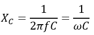
However, the voltage across a capacitor can also be given in terms of its reactance, i.e.,
Thus, the voltage across the capacitor is given by,
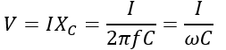
Here, f is the frequency in Hz, ω is the angular frequency, and I is the current through the capacitor.
All these parameters are used to design the voltage divider using the capacitors.
Working of Capacitive Voltage Divider
As mentioned above, a capacitive voltage divider is a circuit that consists of two capacitors connected in series.
The primary function of a capacitive voltage divider is to provide lower voltages from a higher voltage.
As in the capacitive voltage divider circuit shown in the above figure, two capacitors, C1 and C2, are connected in series and provide two low voltages by splitting the applied voltage.
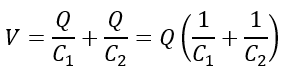
Therefore, according to KVL, we can write,
Where V1 is the voltage across capacitor C1, and V2 is the voltage across the capacitor C2.
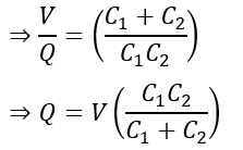
For capacitor,
Since the capacitors are connected in series, the charge and current flowing through them are the same.
Thus, the voltage across the capacitor C1 is given by,
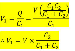
Similarly, the voltage across the capacitor C2 is given by,
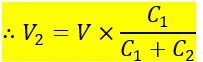
Hence, we can see that the voltage across a capacitor in a capacitive voltage divider is equal to the product of the total supply voltage multiplied by another capacitance divided by the sum of the two capacitances.
Applications
The following are the applications of capacitive voltage dividers.
- It is used to reduce the high voltage to a measurable voltage level.
- Suitable for fast-rising voltages & pulses measurement
- It is used to measure the resistance of the sensor in the microcontroller.
- It is used as a logic level shifter circuit for interfacing various operating voltages.
- These are used in Colpitts Oscillator circuits to capacitive touch-sensitive screens.
- Capacitive voltage dividers are widely used in electron beam accelerators.
- They are used to measure the high voltage in metering and protection PTs(Potential transformers).
Advantages
The advantages of a capacitive voltage divider are-
- Cheap
- Low heat loss.
- It can work either on AC or DC.
- Low Installation cost
- Frequency-dependent
- Fast Response
- Wide Bandwidth
Disadvantages
The following are the disadvantages of capacitive dividers.
- Quite heavy
- Working efficiency gets reduced on overheating
Let us take a numerical example to understand how the capacitive voltage divider works.
Solved Problem on Capacitive Voltage Divider
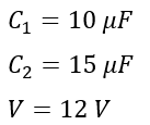
Example 1: A capacitive voltage divider has two capacitors of 10 µF and 15 µF capacitances. Suppose a voltage source of 12 volts AC is applied to the voltage divider. Find the voltages across the capacitors.
Solution – Given,
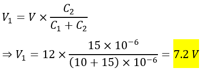
Then, the voltage across the capacitor C1 is,
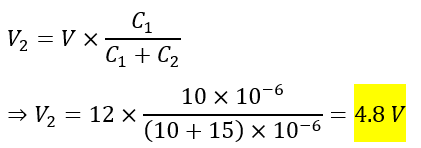
The voltage across the capacitor C2 is
Example 2: A capacitive voltage divider is used to reduce the bus voltage, as shown in the below figure. Calculate the voltage across capacitor C2.
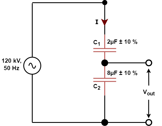
Given Data-
Vbus= 120 kV
f= 50 Hz
C1 = 2µF+/- 10 %
C2 = 8 µF +/- 10%
Vout =?
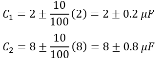
The value of C1 and C2 are,
Sum of capacitance C1 +C2 is;
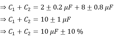
Therefore,
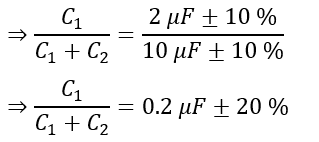
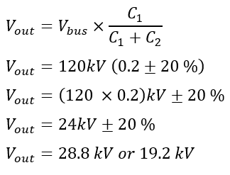
The voltage (Vout) across C2 is;
Hence, this is all about the capacitive voltage divider and its working.