A Colpitts oscillator is an electronic circuit that generates a continuous sinusoidal waveform, typically in the radio frequency (RF) range. It is named after Edwin H. Colpitts, the American engineer who invented it.
A Colpitts oscillator consists of two capacitors and one inductor in the tank circuit or feedback network. The Colpitts oscillator circuit is similar to the Hartley oscillator, using both inductive and capacitive components in its tank circuit. However, the key difference between the two oscillators is how the components are connected.
The Colpitts oscillator is widely used in various applications, including RF communication systems, signal generators, and electronic testing equipment.
Principle of Colpitts Oscillator
The Colpitts oscillator is based on the principle of LC resonance. It comprises a combination of capacitors (C1 and C2) and an inductor (L) connected in a feedback loop. The LC tank circuit determines the oscillation frequency, while the capacitors (C1 and C2) provide the necessary phase shift for positive feedback.
In a Colpitts oscillator, two capacitors are connected in series, and the component inductor is connected in parallel with the junction between these capacitors. In contrast, the inductor is tapped in the Hartley oscillator, meaning a connection is made at a specific point along the inductor coil to create the feedback needed for oscillation.
Therefore, the tank circuit forms a phase reversal network. Colpitts oscillators are used in applications requiring high-frequency sinusoidal oscillations, commonly reaching frequencies up to 100 MHz in commercial signal generators.
Before we discuss the circuit setup of a Colpitts oscillator, let us first understand how the tank circuit works.
Colpitts Oscillator Tank Circuit
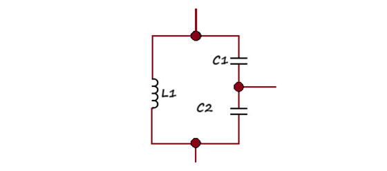
A tank circuit typically consists of an inductor and a capacitor (or multiple capacitors) connected in a feedback loop. The capacitors are connected in series, and their common connection is grounded. This arrangement forms a resonant circuit that can generate a sine wave oscillator signal.
The values of capacitors C1 and C2 are chosen to set the frequency and amplitude of the sine wave oscillator. The ratio of these capacitors affects the resonant frequency of the tank circuit and, thus, the oscillator’s output frequency. Additionally, the specific values of these capacitors can impact the feedback gain, affecting the amplitude and stability of the oscillator’s output signals.
When the capacitors are connected in series, their total capacitance is not simply the sum of their capacities. Instead, the total capacitance is determined by the inverse of the sum of the inverses of their capacitances.
The formula for capacitors in series describes this relationship
1/Ct = 1/C1+1/C2.
This means that the total capacitance (Ct) of the series connected capacitors is inversely proportional to their values.
It is more accurate to say that the total capacitance of the tank circuit in this series-connected configuration is determined by the formula mentioned above.
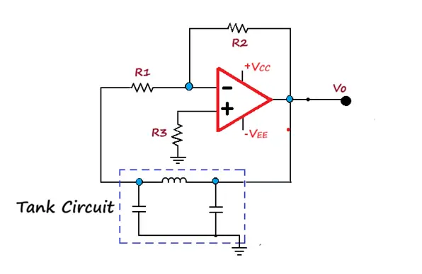
Colpitts oscillator
The Colpitts oscillator consists of two main sections: the amplifier section and the tank circuit. However, the Hartley oscillator also has these sections. In the Colpits oscillator, the tank circuit provides the required phase shift, typically around 180 degrees, but the amplifier section does not produce an additional phase shift. The combination of the tank circuit and the transistor amplifier results in positive feedback, sustaining oscillations.
In the Colpitts oscillator, transistor biasing is typically achieved through a proper DC biasing arrangement (like a voltage divider), not by noise voltage. The transistor operates in its active region to provide gain for the oscillation. However, the process of charging and discharging is due to the tank circuit’s inherent properties (Inductor L and capacitors C1 and C2), not the power supply alone.
The oscillations are applied to the transistor at the base-emitter junction and then amplified and shifted in phase. The amplifier section’s purpose is to provide the necessary gain and feedback to sustain oscillations in the tank circuit.
The output of the amplifier results in sustained, un-damped oscillations. This is the main purpose of the Colpitts oscillator.
Frequency of Colpitts oscillator
The frequency formula for the Colpitts oscillator is provided by the frequency of the oscillations in the Colpitts oscillator is given by
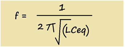
The formula shows the relationship between the frequency (f), the inductance (L), and the effective capacitance (Ceq) of the tank circuit. It is important to note that the frequency of oscillation depends on both the inductance and the equivalent capacitance.
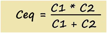
The formula for Ceq, which calculates the equivalent capacitance of capacitors C1 and C2 in parallel, is also accurate.
The Colpitts oscillators, like other LC oscillators, can be tuned by varying the inductance or capacitance of the circuit. The capacitance ratio affects the frequency range over which the oscillator can be tuned. It is essential to maintain this ratio to achieve stable operation.
To achieve this specific ratio (100:1), a special large-value variable capacitor may indeed be required. This is because achieving such a precise ratio with discrete fixed capacitors can be challenging.
The Colpitts oscillators are often used to generate fixed frequencies due to the difficulty of achieving precise and smooth tuning with inductance variations. This is an important practical consideration in oscillator design.
Advantages
- Colpitts oscillator circuitry is simple.
- The frequency of the oscillation in the Colpitts oscillator can be variable; the values of components in the circuit often determine it. Provide constant output amplitude.
- It typically consists of just a few components, including resistors, capacitors, and a Transistor or operational amplifier.
- Colpitts oscillators provide good frequency stability, making them suitable for applications with a stable frequency source.
- The Colpitts oscillator is a versatile circuit widely used in RF applications because it generates stable and tunable sinusoidal signals.
- Its construction and operation are based on LC resonance and positive feedback, making it an essential component in modern electronics.
Disadvantages
- Colpitts oscillators are known for producing oscillations with high harmonic content.
- It does not obtain a pure sine wave.
Applications
Colpitts oscillators find applications in various electronic systems
- Colpitts oscillator is a type of oscillator commonly used in radio frequency (RF) applications to generate carrier frequencies for radio transmitters and receivers.
- They are used in signal generators to produce stable and tunable sinusoidal waveforms for testing and calibration.
- They serve as local oscillators in superheterodyne receivers, helping in the down-conversion of RF signals.
- Colpitts oscillators are used in frequency synthesizers to generate precise and stable frequencies for tuning RF devices.
- They serve as fundamental building blocks when various electronic circuits where stable oscillating signal is required.
Related Artticles:
Thank you . The information was helpfull