Learn about isolators used in substations, their definition, types, parts, and importance for electrical safety and reliability. Discover how isolators ensure safe maintenance and protect personnel in electrical systems.
Definition
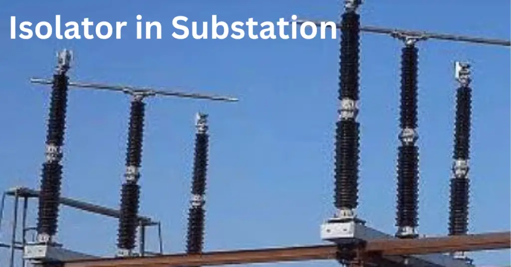
An isolator is an essential device in electrical substations. Its primary function is to ensure the safety of personnel and equipment by disconnecting a part of the circuit when it is not in use. Unlike circuit breakers, isolators do not have a mechanism for extinguishing arcs. They are used to open a circuit under no-load conditions, providing a visible gap.
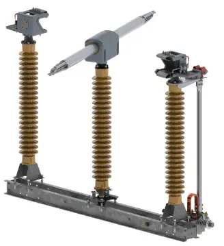
Types of Isolators used in substation
Isolators in substations come in various types and are designed to meet different system requirements and layouts. Here are the main types:
Single Break Isolator
- System Requirement: Used in systems where a single break is sufficient to isolate the circuit.
- Layout Consideration: Simple design, easy to install and maintain.
Double Break Isolator
- System Requirement: Provides two breaks in the circuit for higher reliability and safety.
- Layout Consideration: These isolators require more space in the substation than space required for single-break isolators but offer enhanced safety.
Pantograph Isolator
- System Requirement: Used in high voltage applications where reliable isolation is crucial.
- Layout Consideration: Vertical movement reduces the horizontal space requirement, suitable for compact layouts.
Mating Type Isolator
- System Requirement: Ensures simultaneous disconnection of multiple circuits.
- Layout Consideration: Requires careful alignment but offers efficient multi-circuit isolation.
Parts of an Isolator
Isolators used in the substation consist of several key parts, each playing a vital role in their operation:
- Blades: The main conducting part that opens or closes the circuit. In an open position, the blade provides a visible gap ensuring the circuit is isolated.
- Contacts: These are the points where the blades connect to complete the circuit. High-quality contacts ensure reliable and low-resistance connections.
- Insulators: Made of porcelain or composite materials, insulators support the conducting parts and prevent electrical leakage to the ground.
- Technical Detail: The selection of these insulators depends heavily on the pollution levels of the substation site. As a professional engineer, you must ensure the creepage distance (measured in mm/kV) is sufficient to prevent surface tracking and flashovers, especially in coastal or industrial environments.
- Operating Mechanism: This includes the manual or motorized system used to open or close the isolator. It ensures smooth and controlled operation.
- Base Frame: Provides structural support for the isolator. It must be sturdy to withstand mechanical stresses during operation.
- Earthing Switch: An optional part that grounds the isolated section to ensure safety during maintenance. It prevents any accidental energizing of the circuit.
- Safety Interlocking: The earthing switch is mechanically or electrically interlocked with the main isolator. This ensures the earth switch can only be closed when the isolator is fully open, preventing a dead short-circuit on a live line.
Standard Performance Ratings (IEC 60947-4-1)
When designing a switchyard or selecting an isolator, engineers must ensure the equipment meets the specific thermal and mechanical stresses of the system. Below are the typical ratings per IEC standards.
| Parameter | Standard Value (Typical) |
| Rated Voltage | 11kV, 33kV, 132kV, 220kV, 400kV |
| Short-time Current | 25kA or 40kA (1 or 3 seconds) |
| Insulation Level | Standard Basic Insulation Level (BIL) as per IEC |
| Operating Time | ~2 to 5 seconds (motorized operation) |
Standard Operating Procedure (SOP) for Isolation
Following a strict switching sequence is mandatory to prevent equipment damage and ensure personnel safety. Below is the standard engineering procedure for isolating a substation bay.
- Open the Circuit Breaker: Interrupt the load current using the circuit breaker, designed to quench the electrical arc safely.
- Check Current: Verify zero current on the ammeter or SCADA interface to confirm the circuit is de-energized.
- Open the Isolator: Create the visible air gap required for physical isolation.
- Close the Earth Switch: Discharge the capacitive voltage from the isolated section to the ground.
Maintenance and Commissioning Tests for Substation Isolators
To ensure long-term reliability and prevent catastrophic failures in the switchyard, regular maintenance and testing are mandatory. As a professional practice, the following tests are conducted during commissioning and periodic shutdowns:
- Contact Resistance Measurement (CRM): This test measures the resistance across the main contacts in micro-ohms. High resistance indicates oxidation, loose connections, or pitting, which can lead to overheating under load.
- Insulation Resistance (IR) Test: Performed using a Megger to ensure the dielectric strength of the post insulators. This detects any internal cracks or surface contamination that could lead to leakage current.
- Operational & Alignment Check: Verification that the moving blades enter the fixed contacts centrally and simultaneously (for 3-pole units). Proper alignment prevents mechanical stress on the insulators and ensures a low-resistance path.
- Interlock Verification: A critical safety check to ensure the electrical and mechanical interlocks with the associated Circuit Breaker and Earth Switch are functioning correctly according to the logic scheme.
Conclusion
Isolators are crucial for ensuring the safety and reliability of electrical substations. They provide a visible break in the circuit, confirming that it is safe to perform maintenance or repairs. Understanding the different types of isolators and their parts helps choose the right one for specific system requirements and layouts. Proper installation and maintenance of isolators are vital for the efficient and safe operation of electrical substations.
Read Next: