This article explains the electrical substation components, including lightning arrestors, insulators, relays, capacitor banks, switchyards, busbars, and transformers.
An electrical substation transforms the high voltage to low voltage or vice versa for reliable and efficient electricity distribution to consumers. They maintain the stability and security of the grid by monitoring and managing power flows. A substation has protection devices that safeguard the electrical system against faults, ensuring the power quality delivered to customers meets regulatory standards.
Different electrical substations include generation, pole-mounted, indoor, outdoor, converter, distribution, transmission, and switching substations. In some cases, such as thermal plants, hydroelectric plants, and wind farms, a collector substation enables power transfer from multiple turbines to a single transmission unit.
These substations perform different functions within the power system. Generation substations increase the generated voltage for efficient long-distance transmission, transmission and sub-transmission substations control power flow between different voltage levels, and distribution substations reduce the voltage for residential, commercial, and industrial consumers. Regardless of their type, substations contain essential components such as transformers, circuit breakers, isolators, relays, busbars, and protection systems.
For a detailed classification of generation, transmission, distribution, switching, converter, and collector substations, refer to our guide on Types of Substations.
Single Line Diagram of Substation
The following single line diagram (SLD) shows the typical arrangement of major substation components. It illustrates how electrical power flows from the incoming transmission line through protection and switching equipment to the power transformer and outgoing feeders.
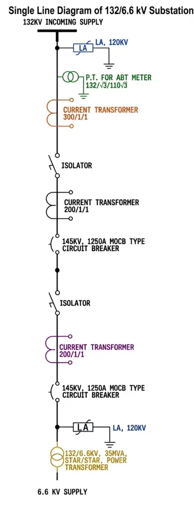
The SLD includes important components such as the power transformer, current transformer (CT), potential transformer (PT), circuit breaker, isolator, busbar, and lightning arrester, which are explained in detail in the following sections.
Electrical Substation Components
The substation components, like isolators, bus bars, power transformers, etc., are interconnected. These components are crucial for the installation of the substation.
Electrical substation designing is a highly complex process that requires careful planning and engineering expertise. The key steps involved in the substation design process are selecting and placing switching systems, planning and arranging equipment, structural design, electrical layout design, protection system design, equipment ratings, and the ordering and installation of various components.
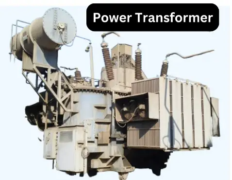
Power Transformer
The power transformers are crucial components of the substation. Step-up and step-down power transformers are mainly used in the substations to change the voltage level. The step-up voltage transformers are installed at the generating station to raise the voltage for long-distance electric power transmission. The step-down transformer is used at the distribution substation to lower the voltage to the utilization level.
The power transformer rating and type are selected based on the power to be handled through the transformer. The power transformer rating above 5 MVA is oil-immersed, natural, or forced-cooled. The transformer oil BDV and Dissolved gas analysis (DGA) test must be done to ensure the trouble-free operation of the immersed transformer. Dry-type transformers of a significant rating are also available nowadays and are used to lower the voltage at distribution substations.
The selection of the transformer is crucial for the stability of the power system. The rating of the transformer is calculated in apparent power (VA,kVA, MVA), and the percentage impedance of the transformer is selected based on the fault level of the electrical network.
The power transformer installed at the generating station should have low copper loss, and the transformer at the distribution system should have low iron losses. This way, it is possible to achieve a better transformer efficiency.
Instrument Transformer
Instrument transformers are crucial substation components used for measurement and protection purposes. Instrument transformers reduce high currents and voltages to safe and practical levels for measurement and protection. The instrument transformer ratings are generally in order of a few VA because these transformers are connected to low-burden. Instrument transformers’ voltage and current rating are typically 110 volts and 1A or 5A. These transformers feed the circuit’s current and voltage to the protection relay.
There are two types of instrument transformers: voltage transformers and current transformers.
Voltage Transformer
The voltage transformer steps down the voltage from a higher to a measurable level. For example, 132 kV line voltage can not be easily measured without a voltage transformer.
If you design an instrument to read 132 kV, the meter will be very heavy and costlier. The feasible solution is the application of a voltage transformer rating 132kV/110 V. The transformer reduces the voltage from 132,000 to 110 volts, which can be fed to meters and protection relays for measurement purposes. The PT or VT ratio shows the secondary voltage of the voltage. These transformers are available in 220kV/110 V, 132 kV/110V, 66 kV/110V, 33kV/110 and 11kV/110V. The secondary of PT is generally 110 volts.
The voltage transformers, also called potential transformers, are used to measure high voltage for revenue metering and protection purposes. Protection and metering are two main types of potential transformers based on their accuracy classes. The voltage transformers based on their construction are- Electromagnetic Potential Transformers and Capacitive voltage transformers(CVT)
Current Transformer
A current transformer (CT) changes the magnitude of higher current to lower for measurement and protection purposes. The CT ratio is a term used to express the secondary current in CT concerning its primary current. For example, A CT with a CT ratio of 1000/5 means the CT secondary will be five ampers if the primary current is 1000 ampers. There are three classes of current transformers.
- Metering Class CT: These CTs are used for energy metering applications, and these CTs have low errors at even low loads. The classes of these CTs are 0.1, 0.2, 0.2s, 0.5 and 1.0.
- Protection class CT: These CTs are used to safeguard the electrical networks. The protection class CTs have higher knee point voltage and do not saturate at higher fault currents. These protection class CTs are marked as 5P10, 5P20, 10P20 etc.
- PS Class CTS: These are special protection class CTs used for differential protection of transformers and generators.
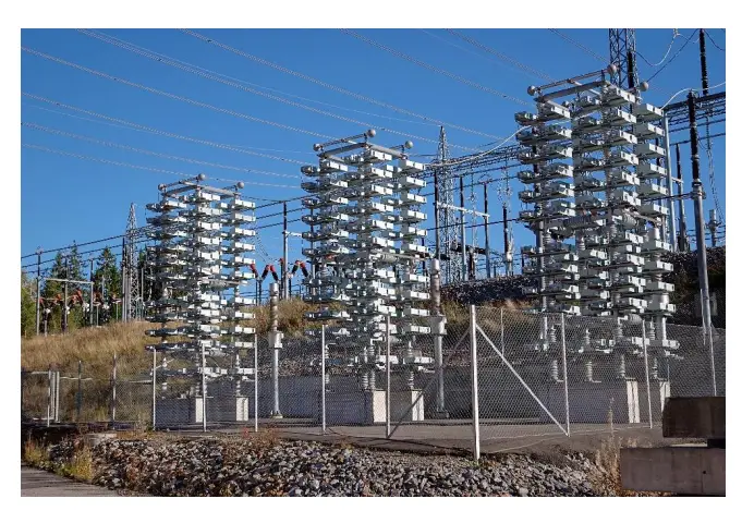
Lightning Arrester
A Lightning Arrester protects electrical and communication systems from lightning strikes. During lightning, a high voltage is induced on a transmission line, and if not diverted, the induced voltage can damage the electrical equipment connected to the power system. The lightning arresters are installed at the incoming side of the switchyard to bypass the lightning current to the ground. The lightning arrester impedes the flow of power frequency current and passes the lightning frequency voltage to the ground. Thus, the lighting arresters are the protective component of electrical substations.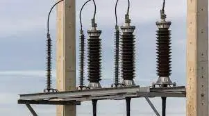
There are various types of lightning arresters, such as Electrolytic arresters, Rod Gap Arrester, Expulsion-type lightning arrester, Valve-type lightning arresters, Metal-Oxide Lightning arresters, Oxide film arresters, Sphere-Gap Arresters, Horn-Gap Arrester, Multiple gap arrester, Impulse protective gap, Thyrite lightning arrester. and Autovalve arresters.
Wave-Trapper
The wave trapper is placed on incoming power lines to capture high-frequency signals. These signals are sent from a remote station and can interfere with the current and voltage signals. The wave trapper is designed to detect and isolate these high-frequency signals, redirecting them to the telecom board for further processing.
Circuit-Breaker
The circuit breakers open and close the electrical circuit in normal operation. The circuit breakers also interrupt the closed circuit in the case of a fault in the electrical system. The circuit breaker breaking current and making current capacity are two crucial parameters, and the breaker selection is based on these two parameters and nominal current carrying capacity.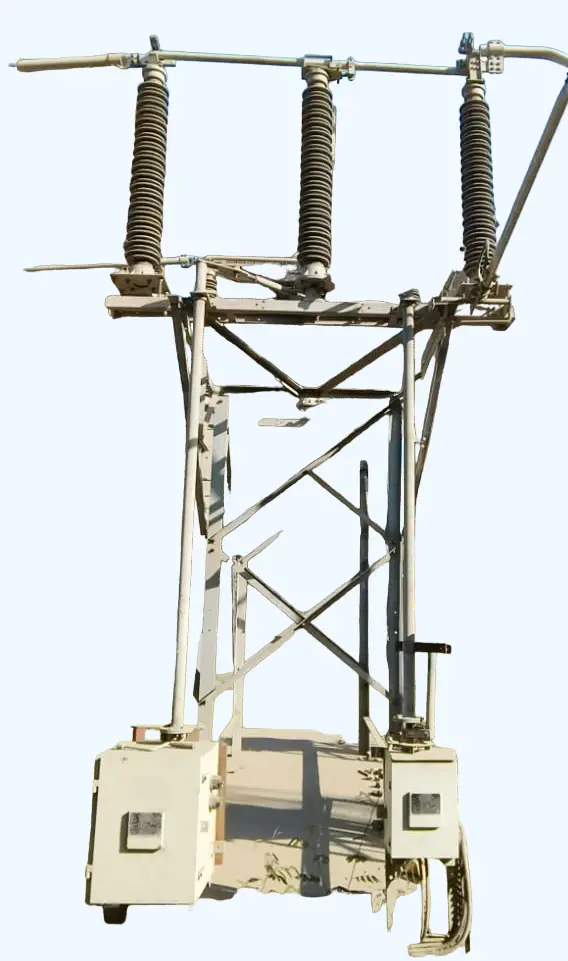
The breakers have fixed and moving contacts and arc quenching medium. During the separation of contacts, the arc quenching medium, such as oil, vacuum, or SF6 gas, quenches the arc formed between these contacts. In the case of fault, the protection relay sees the fault and outputs a contact to trip a circuit breaker.
There are various types of circuit breakers based on arc quenching methods. These are oil circuit breakers, vacuum circuit breakers, Air blast Circuit Breakers, and SF6 circuit breakers.
Bus Bar
An electrical busbar is made of a metallic conductor in a bar or strip shape and enclosed in switch gear, panel boards, and busway enclosures. The busbar has a group of conductors that carry the circuit current, and its sizing is crucial for the reliable operation of the electrical system.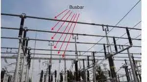
The bus bar is arranged in a pattern of single busbar, double busbar, and ring busbar as per the need of circuit applications. The materials used for busbars are copper or aluminum.
Isolator in Substation
An isolator is an electrical switch that disconnects a circuit after interrupting the current flow. This switch is called a disconnector or air break switch(ABS). The isolator must be operated when no current flows through it because Isolators are not equipped with arc-quenching devices. These substation components are off-loaded switches. They are sometimes used to break the current charging of the transmission line in certain situations.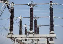
Gang-operated isolators are used to open multiple conductors simultaneously, while single-pole isolators are used to isolate a single-line conductor.
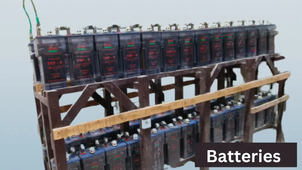
Batteries
Lead-acid batteries supply power to the breaker’s tripping and closing coil and protection relays in substations. The 110 VDC power supply is formed by connecting 55 cells of 2.2 volts in a series. This ensures that the operation and protection of circuit breakers remain uninterrupted even during blackouts of the main power supply.
Switchyard
Switchyards serve as the connection between transmission and generation systems, ensuring that the voltage is kept constant. They transmit power generated from the substation to the nearby transmission lines or power stations at the desired voltage level.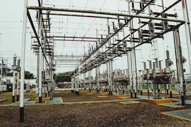
Relay
The relay is a crucial substation component. The protection relay senses the electrical quantities, such as current and voltage, and sends a trip command to the circuit breaker to disconnect the faulty part. The overcurrent and earth fault relays are used for feeder protection. Overcurrent, earth fault, differential protection, over-fluxing, and Buchholtz relays protect the transformer. The relay thus protects the electrical system from damage.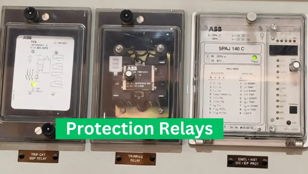
Capacitor Bank
A capacitor bank is a group of capacitors connected in series or parallel combinations. Capacitor banks store reactive energy, which can compensate for reactive energy and improve the power factor. This leads to a more stable grid with higher transmission capacity and fewer transmission losses. The capacitor banks improve the voltage profile in the electrical network.
Carrier Current Apparatus
The carrier current system is installed in substations to enable telemetering, supervisory control, relaying, and communication. The system is connected to the high-voltage power circuit and housed in a carrier room.
Insulator
Line insulators are critical substation components of transmission lines. They prevent electricity leakage from line conductors to pole support and the ground.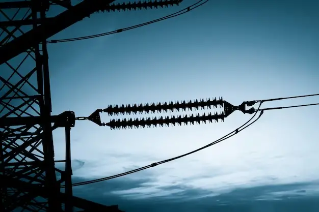
Depending on the line configuration, different power line insulators, such as Pin, Suspension, Strain, and Shackle insulators, are used in overhead transmission lines.
Supervisory Control & Data Acquisition (SCADA) System
The SCADA system enables remote operation and monitoring of substations for automation. This component in the substation allows operators to easily monitor and analyze data.
Load Shedding System
If the demand exceeds the available energy, the generator can trip. In this scenario, the load-shedding system balances the supplied and consumed energy by shedding some loads. This helps maintain the grid stability.
Energy Management System
The Energy Management System (EMS) measures and monitors the energy consumption of all feeders and is integrated with the Load Shedding System to shed load during peak times.
Earthing System in Substation
The earthing system is an essential part of an electrical substation that provides a low-resistance path for fault current and lightning current to flow safely into the ground. All metallic parts of the substation, such as transformer tanks, circuit breakers, support structures, control panels, and equipment enclosures, are connected to the earthing network.
The earthing system generally consists of an earth mat (ground grid), earth electrodes, and earthing conductors buried approximately 0.5 to 1 meter below the ground surface. In transmission and distribution substations, the earth grid resistance is typically maintained below 1 Ω to ensure effective fault-current dissipation.
The major functions of the earthing system are:
- Protection of personnel and equipment during faults
- Safe dissipation of lightning surge currents
- Maintaining equipment at earth potential
- Providing a return path for ground fault current
- Ensuring proper operation of protection relays and circuit breakers
A properly designed grounding system improves substation safety, reliability, and operational performance while minimizing the risk of equipment damage during electrical faults.
GIS vs AIS Substation
Electrical substations are broadly classified into Gas Insulated Substations (GIS) and Air Insulated Substations (AIS) based on the insulation medium used around the equipment.
In an AIS substation, electrical equipment such as circuit breakers, disconnectors, and busbars are installed in open air. AIS substations require more land area but have lower installation costs and easier maintenance.
In a GIS substation, the equipment is enclosed within metal chambers filled with SF₆ gas, which provides excellent insulation. GIS substations require significantly less space and are commonly installed in urban areas where land availability is limited.
| Parameter | AIS Substation | GIS Substation |
| Insulation Medium | Air | SF₆ Gas |
| Space Requirement | High | Low |
| Initial Cost | Lower | Higher |
| Maintenance | Easier | Specialized |
| Reliability | Good | Very High |
| Typical Application | Rural Areas | Urban Areas |
Modern power systems increasingly use Gas Insulated Substations (GIS) in metropolitan regions due to their compact design, high reliability, and reduced environmental exposure.
Conclusion
A substation is a critical part of the electrical power system that enables the efficient transmission, distribution, protection, and control of electrical energy. Various substation components, including transformers, circuit breakers, isolators, instrument transformers, relays, busbars, lightning arresters, and earthing systems, work together to ensure the safe, reliable, and uninterrupted supply of electricity to consumers.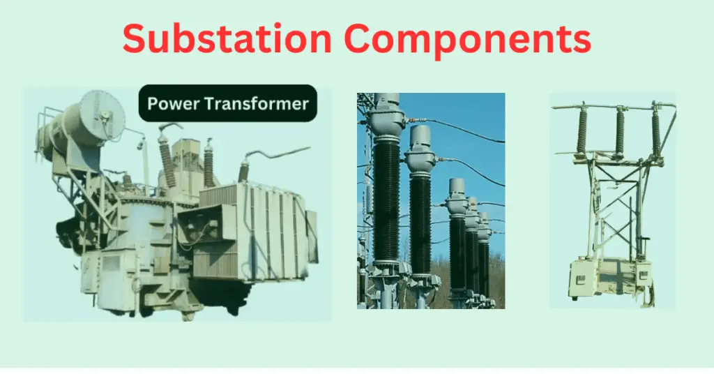
Frequently Asked Questions (FAQs)
A substation transforms voltage levels, controls power flow, protects the electrical network, and ensures the reliable transmission and distribution of electricity.
The main components of a substation include power transformers, current transformers (CTs), potential transformers (PTs), circuit breakers, isolators, busbars, relays, lightning arresters, capacitor banks, and earthing systems.
Power transformers are among the most important components of a substation because they step up or step down voltage levels for efficient power transmission and distribution.
A single-line diagram (SLD) is a simplified representation of a substation that shows the electrical connections between major equipment and components.
A lightning arrester protects substation equipment by diverting lightning surge currents safely to the ground.
Current transformers (CTs) and potential transformers (PTs) are used in a substation for metering, monitoring, and protection by reducing high currents and voltages to safe values.
Read Next: