In AC systems, an instrument transformer measures electrical quantities such as voltage, current, power, power factor, energy, and frequency. Instrument transformers are also used with protection relays to protect power systems.
The main function of an instrument transformer is to reduce the voltage and current of an AC system. Since the voltage and current level of the power system is too high, it is very difficult and expensive to design measuring instruments to measure such a high-level voltage and current. Generally, the measuring instruments are designed for 5A and 110V.
It is possible to measure a large electrical quantities with measuring instruments with the help of an instrument transformer. Modern power systems utilize these instrument transformers, so they are popular.
Types of Instrument Transformers
Instrument transformers are of two types
- Current transformers
- Potential Transformers
Symbols of Current & Potential Transformer
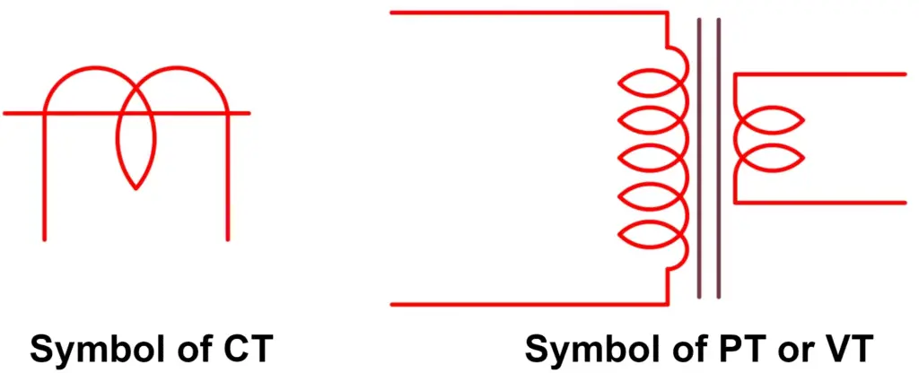
Current Transformer (CT)
The current transformer reduces the current of the power system to a lower level so that it is suitable to measure it with a small-rated ammeter (i.e. a 5A ammeter). The figure below shows a typical connection diagram of a current transformer.
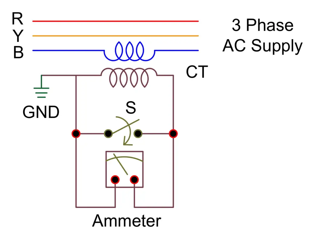
The CT primary has very few turns. The primary is connected to the power circuit in series. Hence, sometimes it is also called a series transformer. The secondary winding has a large number of turns, and it is directly connected to an ammeter. As the ammeter has a very small resistance, therefore, the secondary of the current transformer operated almost in a short-circuit condition.
To prevent high voltages on the secondary, one terminal of the secondary is grounded. Consequently, reduces the chances of insulation breakdown and protects the personnel against high voltage. Furthermore, before disconnecting the ammeter, a switch “S” short-circuits the secondary to prevent high voltage build-up on the secondary, as shown in the above figure.
Caution– CT secondary must not be open when its secondary carries the current.
Types of Current Transformers (CTs)
- Wound-type
- Bar type
- Toroidal

1. Wound-type CT
The primary of a current transformer (CT) is connected directly in the series to the load whose current is to be measured. In this, the primary and secondary cannot be disconnected. Switchyard high voltage current transformer is the best example.
2. Bar type CT
Typically they are made with a copper or aluminum bus bar surrounded by a secondary winding over ferromagnetic cores. The bus bar acts as a single-turn primary winding. Current carrying conductors are directly connected to them. Alternatively, they are called bar-primary current transformers.
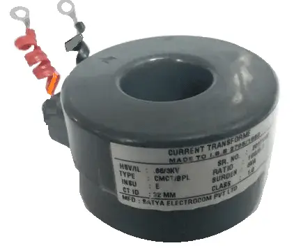
3. Toroidal CT
No primary winding is present in them. Toroidal CTs contain a window or hole through which a line carries current flowing in the network. The secondary of the CT is portable. A The digital Tong tester has toroidal type CT.
Potential Transformer (PT) or Voltage Transformer (VT)
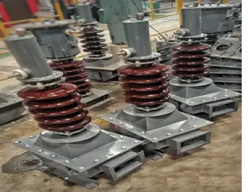
A potential transformer is also called voltage transformer. Its is an instrument transformer used to convert voltage from a higher value to a lower value. It is used to step down the power system voltage to a lower level so that it is feasible to measure with a small rated voltmeter. i.e. 110V 120V.
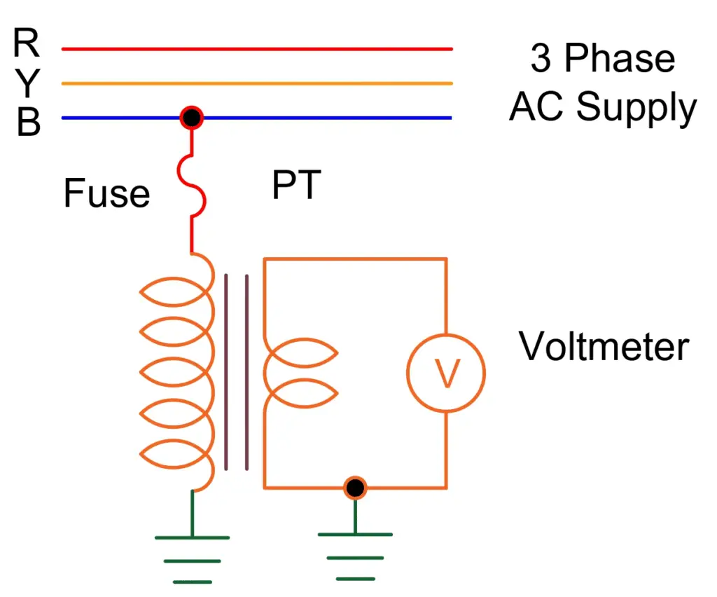
The PT or VT has the same construction as any normal transformer. This reduces the voltage to a safe limit, which can be easily measured by an ordinary low-voltage device, such as a voltmeter.
The number of turns in the primary winding is greater than the number of turns in the secondary winding because it is a step-down transformer. A potential transformer connects across or parallel to the line, which is measured to record ratio or angle errors.
A potential transformer is designed to monitor single-phase switching voltages and three-phase terminals.
The potential transformer is a special type of transformer, with which it is possible to take readings from electrical service connections. The PT or VT is designed to have a lower ratio and phase angle errors for accurate power and energy measurement.
Caution: Do not short circuit the PT.
Types of Potential Transformers (PTs)
Based on their function, they are three types.
- Electromagnetic
- Capacitor
- Protection
1. Electromagnetic Transformer
In the same way as the main transformer, primary and secondary windings are wound on a magnetic center. It is operated at a voltage higher or lower than 130 kV. Phase determines the primary section while ground determines the secondary section. These devices are used in relays, measurements, and high voltage networks.
2. Capacitive Voltage Transformer
Main or secondary windings are connected with a series of capacitors. The capacitor acts as a potential divider and lowers the voltage. This device measures the voltage coming out of the secondary winding. It is also used for power line communications system. It is the most expensive.
3. Protection (Voltage Transformer)
It can be single-phase or tri-phasic and works with the highest precision. It is used to perform and monitor measurement tasks of instruments, relays, and other devices.
The increase in the number of instruments in the relay connected to the secondary power transformer increases the errors. Therefore, the devices must be connected to its secondary as per total VA of the transformer.
Power Metering using CT and PT
The instrument transformers, CT and PT, are used for measurement of power in the circuit. The circuit diagram of the power measurement circuit is shown in the below figure. The CT is connected in the series to the load and the PT is connected in the Parallel to supply system.
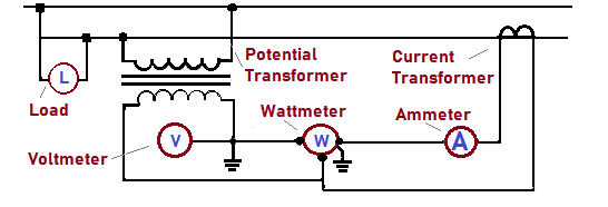
Current transformers (CT) and potential transformers (PT) are together used for power metering from a utility to a customer. Wattage (W) or Power (P) is found by multiplying the current and voltage.
A potential transformer provides a way to measure the voltages, whereas a current transformer provides a way to measure the current. The wattmeter is connected in series with the ammeter and must operate on 5A or less.
Advantages of Instrument Transformers
The large voltage and current of the AC power system can be measured using a small-rated measuring instrument, i.e. 5A or 110V.
By using instrument transformers, measuring instruments can be standardized. Which translates into a reduction in the cost of measuring instruments. Increasingly, damaged measuring instruments can be easily replaced with healthy, standardized measuring instruments.
Instrument transformers provide electrical isolation between the high voltage power circuit and the measuring instruments. This reduces the electrical isolation requirements for measuring instruments and protection circuits and also ensures the safety of operators.
Multiple measuring instruments can be connected via a single transformer to the power system.
Due to the low voltage and current level in the measurement and protection circuitry, there is low power consumption in the measurement and protection circuitry.