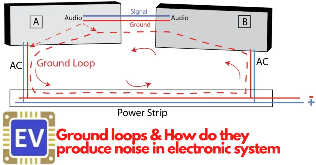
Flowing of electric current through the undesirable paths in an electrical circuit creates ground loops. This phenomenon happens when the electrical piece of equipment has a connection at multiple points on the ground plane.
The ground loops induce noise in instrument signal cables. Also, it can overheat the cables & thus it begets a fire hazard.
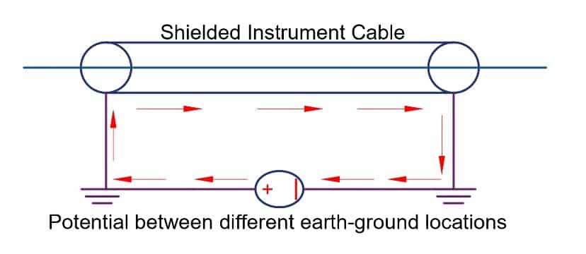
Ground Loop Diagram
The current flow between the two ground points because of ground loops. It is shown in below ground loop diagram.
Causes of Ground Loops
There are several reasons for ground loops in any instrumentation installation. Some of the causes are the following.
- Potential difference between the ground terminals of the ground plane
- Inductive coupling
- Capacitive coupling
- Use of internally grounded instruments inside an already grounded loop
- Grounding of the Cable shields at both ends
- Use of Grounded thermocouples with non-isolated transducers
- When four wire transmitters are used as an input to a receiver instrument that has different ground connection
The ground loops create electronic noise in the instrument cables & electronic equipment as well. Therefore, it is a must to eradicate this problem for a reliable operation of the instrument.
The inductive, capacitive & conductive coupling are the major reasons for the noise in the electrical system. We will discuss these coupling briefly to have a basic understanding.
Magnetic coupling
There exist some magnetic or capacitive coupling when the circuits share common conductors.
An alternating current-carrying conductor generates a magnetic field around the conductors. Further, this magnetic field produced by one conductor links to another conductor and vice versa. This type of coupling is called magnetic coupling.
The conductor has also finite inductance & it stores the magnetic when there is a change in the current flowing through it.
The noise becomes more predominant when the power cables and instrument cables go through the same duct or conduit. We can reduce the noise caused by magnetic coupling by separately installing power cables & signal cables.
The impedance of the coupling plays a vital role in noise generation. More impedance causes more noise. Therefore, by reducing the impedance of the return wire, it is possible to reduce the noise.
Also, we can reduce the noise by the use of separate return wires for an individual circuit.
Capacitive Coupling
All the conductors form a capacitor because conductors have insulation between them. Upon charging the circuit, the voltage induced by capacitive coupling induces a voltage in the other circuit. Therefore, the lesser capacitive coupling between the circuit is desirable to reduce the noise in the circuit.
How to Eliminate Ground Loops?
There are various methods of mitigation of ground loops. However, two methods are very effective for the mitigation of ground loops.
- Single Point grounding
- Use of Differential Inputs
Single Point grounding
In single-point grounding, the unified ground passes through this plane. Single point grounding comprises grounding of the electronics/instrumentation installation at a single point. In this case, the noise signal that arises from the other grounding points can not interfere. Thus, this approach significantly reduces the noise.
Use of Differential Inputs
The differential inputs approach is most suitable when EMI or RFI noise is generally a problem. The differential inputs cancel out the noise voltage and thus reduce the noise in the system.
Use of Battery Powered Instruments
The use of battery-powered instruments is one of the solutions to eliminate the noise. However, it is not feasible because the battery has a limited life.
Use of Twisted Pair cables
One of the pragmatic approaches to reducing noise caused by inductive coupling is the use of a twisted pair cable. The noise generated by the power & control or signal cable gets nullified. And, it greatly reduces the effects of electromagnetic induction.
The twisting of wires ensures that the two wires are almost at the same distance from the interference source. The noise produces a common-mode signal that can be canceled out at the receiver end by detecting the difference signal.
Electromagnetic induction is reduced because when the wires create a series of loops instead of one large loop, the inductive effects of the external magnetic field tend to cancel out. Thereby, twisted pair cable reduces the induced noise voltage on the instrument signal wires.
Grouping of cables
In this method, the cables used for the grounding loop are grouped into a bundle. The stray magnetic field induces an equal current on both sides. Thus, the current cancels out, and there is no noise in the system.
Read Next: