Resistance & reactance grounding limits the system fault current in the case of the fault. The resistance or reactance or combination of resistance & reactance is added between neutral and ground. These components hinder the path of the fault current and keep the fault current within the safe current limit of the equipment.
What is Resistance Grounding?
In a 3-phase, 4-wire system, the neutral point is at zero potential when all phase currents are equal. However, the imbalance in the line currents causes the voltage to develop at the neutral point. A large current flows if the neutral point is connected to the ground point. The large current is vulnerable to the electrical network and the electrical equipment.
To limit the earth fault current, the resistance- known as Neutral Grounding Resistor– is connected between the system neutral and the ground. The resistance connected between the system ground and ground is known as resistance grounding.
The following are the advantages of resistance grounding.
- Limits the fault current to a safe value
- Improves the system’s stability.
- Reduce the transients
- Minimize the possibility of arcing ground.
- Improves safety
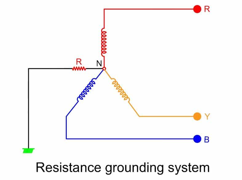
In a resistance grounding system, merely the use of resistance does not guarantee the protection of the electrical network. The right selection of the resistance value is very important for a perfect resistance grounding system.
If we select the resistance value too low, a large current will flow which can damage the system. Contrary to this, if we select the resistance value too high, an infinitesimal current flows through the ground, and the system acts like an ungrounded system.
In a nutshell, a sufficient current, neither too high nor too low, must flow through the ground in order to detect the fault current for onward isolation of the faulty section.
For Which Application Resistance Grounding Suitable?
Resistance grounding is the most suitable when it is necessary to limit the earth fault current to the equipment’s full load current. We know equipment life is affected by the rise in temperature. The large current flowing through the equipment causes temperature rise. Therefore, resistance grounding is a good method to limit the current to the equipment’s safe current rating.
Now, we take an example to understand the concept of resistance grounding.
A piece of electrical equipment rated at 11 kV has a full load current capacity of 1200 amperes.
Case-1 – When there is no resistance grounding
In this case, R =0
Earth pit resistance = 1.0 Ohm
Earth Fault current = Neutral to Phase Voltage/ Earth pit Resistance
= (0.58 x 11) / 1
= 6380 A
Case-2 – When there is resistance in system grounding
Now, we connect 5 Ohms resistance between the neutral and ground.
Total resistance = Connected resistance + Earth pit resistance
Rt= 5 + 1 = 6 Ohms
Earth Fault current = Neutral to Phase Voltage/ Total Resistance
= (0.58 x 11) / (5+1)
= 6.38 /6
=1006 A
In case 2, the current reduces to 1/6 th of the current in case no.1. After resistance grounding, the current is well below the equipment’s full load current capacity.
Thus, from the above discussion, it is possible to limit the earth fault current by adding the resistance between the neutral and the earth. The current transformer detects the earth fault current, and the protection relay automatically isolates the faulty section.
Do we need a neutral grounding system for the 440 Volts system?
For 440 volts system, the magnitude of the earth fault current is;
Earth Fault current = Neutral to Phase Voltage/ earth pit resistance
= (0.58 x 440) /1
= 255 A
The magnitude of the earth fault current is low for a 440-volt system. Therefore, this system does not require a resistance grounding system.
Therefore, the solid grounding system is sufficient for a 440-volt system.
Reactance Grounding
The inductor has an inductive reactance that opposes the flow of electric current. And we can use an inductor to limit the fault current. The inductor connected between the neutral and the ground forms a reactance grounding.
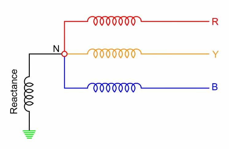
The selection of the reactance is important for making the reactance grounding effective. Neither a small value reactance nor a large value reactance is a perfect selection of the neutral reactance grounding. Therefore, the proper selection of reactance is a must for a perfect reactance grounding.
The reactance grounding is most effective for long transmission line and cable systems. The current through the reactance during fault should be within the limit of 25% of the 3-phase fault current to minimize transient over-voltages.
Read Next:
very nice one
Thanks