This article describes the percentage impedance of the transformer & its calculation. In this article, we will learn what is percentage impedance and how to calculate it.
What is the Percentage Impedance of the Transformer?
The transformer has primary and secondary winding made up of copper or aluminum. The primary and secondary winding has many turns. The resistance of the winding depends on the length of the wire used.
The transformer works on AC supply. When AC supply is fed to the primary the flux is generated, however entire flux does not link to both winding and some mount of flux leaks. The leakage flux is denoted by leakage reactance in the transformer. Thus the transformer winding has resistance and reactance or in other words, we can say transformer primary and secondary has impedance. The secondary impedance can be transferred to the primary to get the equivalent impedance of the transformer.
When the supply is fed to the transformer, the impedance of the transformer opposes the current, and a voltage drop takes place in the winding. The voltage drop in the transformer has a direct relationship with the impedance or percentage impedance of the transformer.
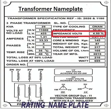
The percentage impedance of the transformer is engraved in the nameplate of the transformer.
Definition of percentage impedance of Transformer
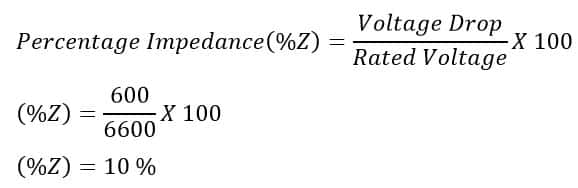
When the transformer is fully loaded up to its rated secondary current, the voltage drop takes place due to transformer winding resistance and reactance. The voltage drop is expressed in terms of rated voltage is called the percentage impedance. If the primary winding rated at 6600 Volts is fully loaded, and the measured voltage drop is 600 Volts, then the percentage voltage drop is 10% and, thus the transformer percentage impedance is 10%.
So we can say, the percentage impedance of a transformer is the percentage voltage of the rated voltage required to circulate rated current flow through one transformer winding when the other winding is short-circuited at the rated tap position of the transformer.
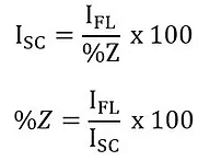
The impedance of the transformer, expressed as the percentage of the rated impedance of load at full rated current, is called percentage impedance. This impedance is calculated from short circuit test data when a small primary voltage produces a full load current in the secondary of the transformer. This small voltage on the primary side, expressed as a percentage of full rated voltage, is called percentage impedance.
Percentage Impedance Formula?
How to Calculate Percentage Impedance of Transformer?
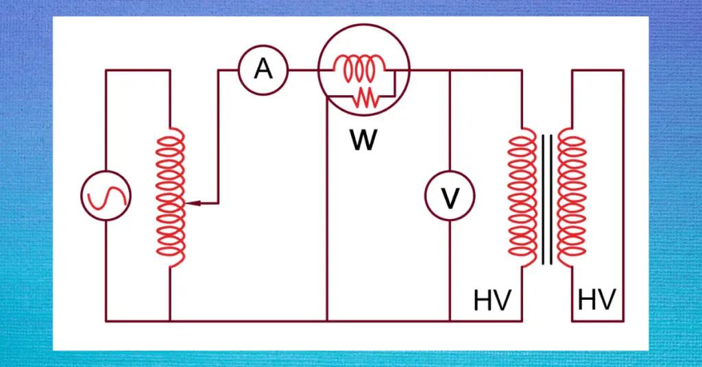
The percentage impedance of the transformer can be calculated by conducting the short circuit test of the transformer. The secondary winding is short-circuited and voltage is applied to the HV side of the transformer. The full rated voltage at the HV side should not be applied to the primary side, it may damage the transformer. In this case, an enormous short circuit current will flow in the winding and the transformer may damage.
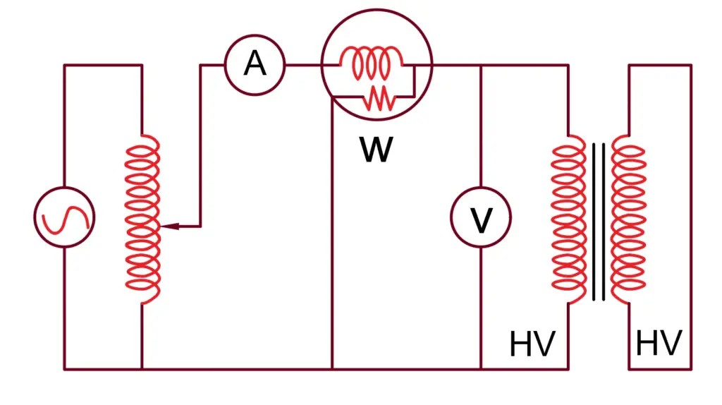
The voltage at the HV side must be increased gradually starting from zero volts. Increase the voltage gradually till the current in the secondary side reaches up to the secondary full load rated current. Note down the primary voltage(V) at the secondary current is equal to the full load current of the transformer. The percentage impedance formula of the transformer is;
% Z of transformer =( V/Vr) X 100
Where,
Vr = Rated voltage of the primary
V = Primary voltage at which secondary current= FLC of secondary
Solved Problem on Percentage Impedance of Transformer
A transformer of rating 132000/6600 volts transformer has a measured impedance drop of 600 volts. What is the percentage impedance of the transformer?
By measuring the current of the HV side and voltage drop across the secondary side, the primary and secondary impedance can also be calculated. The current in the primary is 70 ampere, and the impedance of the transformer is;
Z = 600/70 = 8.57 Ω
Can we choose the percentage impedance at the design stage?
There are two types of loading considered during the design stage- electrical loading and magnetic loading. If magnetic loading is increased, fewer turns are required for primary and secondary winding, and as a result percentage voltage drop will decrease. However, there is a limitation of magnetic loading on the transformer. The CRGO core can work up to 1.9 Tesla. The designer designs the transformer at 1.7 Tesla taking a 10 % margin for over-fluxing. Therefore, more or less the percentage impedance of the transformer for a particular rating will be as per the Indian electricity standard or another standard.
The percentage impedance can be slightly decreased by lowering the leakage flux by selecting the quality material for the transformer. The percentage impedance of the transformer has a significant impact on the power system. When the transformer is rewound, the % impedance must be as per standard because the % Z increase with smaller diameter wire of winding, impure copper, etc.
Let us see, how the percentage impedance affects the power system.
Role of Percentage Impedance in Short Circuit Calculations
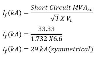
The impedance of the transformer limits the fault current. The higher the percentage impedance lower will be the fault current magnitude. The fault current of the system can be expressed with the following mathematical expression.

A 132/6.6 kV, 30 MVA transformer has an impedance of 9 %. The fault level at the secondary side of the transformer is ;
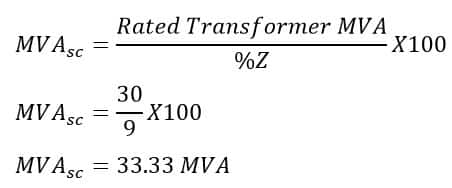
Transformer fault current.
Thus, the percentage impedance of the transformer has a positive as well as a negative effect on the power system.
- If the percentage impedance is less, the fault MVA of the network is more. All the switchgear like breakers, CTs, and Isolators need to be of higher short circuit capacity and, thus cost will increase. However, a positive point of lower % impedance is better voltage regulation of the system.
- If the percentage impedance is high, the fault MVA is less. However, voltage regulation will be poor.
Therefore, the optimum percentage impedance of the transformer is selected to have a better trade-off between fault level and voltage regulation.
Role of Percentage Impedance in the Parallel Operation of Transformers
Transformers are operated in parallel to the optimum utilization of the transformer. It is desired that both transformers must share the load equally to avoid the circulation of current from one transformer to other transformers. The transformer has maximum efficiency at about 40 % loading, therefore if the transformers are operated in parallel the efficiency of both transformers improves. However, for equal sharing of the load, the ratio of transformer rating to percentage impedance must be equal for both transformers.
Suppose the ratio of transformer rating to percentage impedance is unequal. In that case, one transformer will get loaded more than the other transformer, and also circulating current will flow in the transformer will cause additional power loss and efficiency deterioration of one transformer.
Transformer Permissible Percentage Impedance as per Indian standards/ IEC 60076
The transformer percentage impedance for different MVA and kV ratings is specified in the standard. However, after manufacturing of the transformer +/- 1 % deviation is allowed. For example % Z for 33 MVA,132/6.6 kV transformer is 13%, and the transformer % impedance can be in the range of 13 +/- 1%. At the time of testing after manufacturing, the percentage impedance of the transformer should be in the range of 12.87 % to 13.13%.
It is an interesting clarification the you have given for the percentage impedance of transformer .
thank you