Leakage Reactance of Transformer
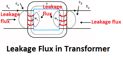
The flux generated in the primary winding of the transformer gets linked with both the primary and secondary winding. However, all the flux generated does not link with both the primary and secondary winding.
A small portion of flux will link either winding but not both. The flux which does not link with both the primary and secondary winding is called leakage Fluxin transformer. The leakage flux cause self reactance in the concerned winding.
The self reactance is also called leakage reactance. The transformer winding also has a certain resistance. The combination of the resistance and the leakage reactance called impedance of the transformer winding cause voltage drop in the primary and secondary winding.
Resistance of Transformer
The primary and secondary winding of the transformer is made of copper or aluminium. Copper is widely used as a winding material for coils and winding. Copper is a very good conductor of electricity because it has lower resistance compared to aluminium. However, the copper does not have zero resistance, even the resistance of copper increase with an increase of temperature.
Thus, the winding resistance can not be zero in any case, and therefore, the primary and secondary winding of the transformer has some resistance. The resistance of the winding depends on the specific conductivity of the material, the number of turns, and the area of the conducting material.
So primary and secondary winding has some resistance. This total internal resistance of both the primary and secondary winding is known as the resistance of the transformer. The secondary winding resistance can be referred to at the primary side, and also the primary winding resistance can be referred at the secondary side.
The transformer total resistance if the secondary resistance is referred in the primary side,

Where, K is the turn ratio and K = N2 / N1
Impedance of Transformer
The primary and secondary winding of the transformer has both leakage reactance and resistance. The leakage reactance and the resistance can not be zero for a practical transformer. The combination of resistance and leakage reactance is called the impedance of the transformer. If R1 and R2 and X1 and X2 are primary and secondary resistance and leakage reactance of transformer respectively, then Z1 and Z2 impedance of primary and secondary winding are respectively,
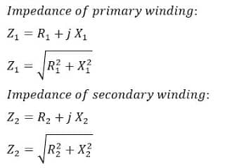
The voltage drop in transformer winding depends on the impedance of the transformer.
Leakage Flux in Transformer
In an ideal condition, the leakage flux in the transformer should be zero. However, there would be some part of the flux that does not link to both the primary and secondary winding and thus, some part of the flux remains unutilized. The leakage flux pass through the winding insulation instead of passing through the core. The leakage flux produces leakage reactance in both the primary and secondary winding of the transformer. This phenomenon in transformers is known as Magnetic leakage.
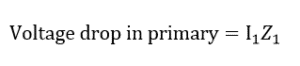
The voltage drop takes place in the winding due to the impedance of the transformer. If voltage V1 is applied across the primary of the transformer, there will be a voltage drop I1X1 in the primary to compensate the primary self-induced emf due to leakage reactance. Let X1 be the primary leakage reactance. The voltage equation at the primary side of the transformer is:
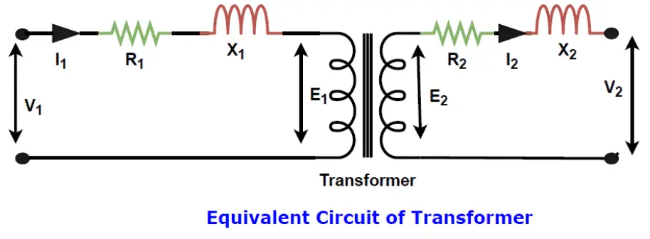
If we apply AC voltage V1 across the primary of the transformer, the voltage drop in the primary takes place caused by voltage drop because of leakage reactance and resistance. Let the primary current be I1. The voltage equation at the primary side of the transformer is as given below.
Voltage drop in the primary due to primary resistance and leakage reactance is;
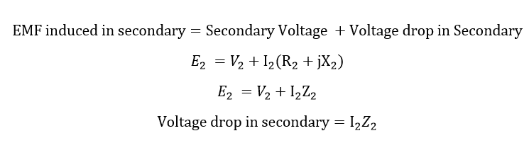
Similarly, the transformer supplies current to load. Let the secondary current be I2. The secondary resistance and reactance are R2 and X2 respectively.EMF induced in the secondary is E2.
Read Next: