The induction motor can’t run if there is no slip. What is a slip of an induction motor? Let us first understand the slip of the induction motor.
What is Slip?
When the induction motor is fed with a three-phase supply, a rotating magnetic field is produced. The speed of the rotating magnetic field is known as the synchronous speed(Ns) of the motor. The magnetic field produced in the motor gets linked to the rotor conductors, which are short-circuited by the end rings.
The linked flux to the rotor conductors induces a voltage in the rotor, and as the rotor conductors are short-circuited, the current starts flowing through them. Due to an interaction between the magnetic field and the rotor current, the torque is produced, and the rotor starts rotating. Let the rotating speed of the rotor be N.
In an induction motor, the rotor speed always lags the synchronous speed of the rotating magnetic field. The induction motor is called an asynchronous motor because the actual speed of the motor is always less than the synchronous speed of the motor.
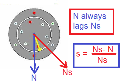
The difference between the speed of the rotating magnetic field or synchronous speed and the actual speed of the rotor or motor is known as the slip of the motor. The slip can be mathematically expressed as;
s = Ns – N
The slip is in RPM.
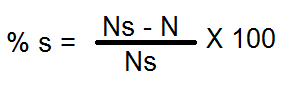
Percentage slip,
For example :
A 4 pole,50Hz induction motor having 1480 RPM at full load.
Synchronous Speed of Motor
Ns = 120f/P
= 120 x 50/4
Ns = 1500 RPM
s = Ns -N
= 1500-1480
s = 20 RPM
% slip = [(Ns-N) /Ns] x 100
= [(1500-1480) /1500] x 100
= [20 /1500] x 100
% slip =1.33 %
Read More: Induction Motor Slip Calculator
Why Slip is a must for the operation of an Induction Motor?
The torque is produced when the current flows in the rotor conductor. If the slip is zero, no EMF will be induced in the rotor conductor, and hence, there will be no flow of the current in the rotor circuit.
The torque is produced due to an interaction of the main flux and the rotor current. If the rotor current is zero, the motor will produce no torque. In the absence of the slip, the operation of the motor is not possible. The torque produced in an induction motor is proportional to the slip. The torque equation of the induction motor is given below.
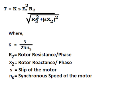
From the above torque equation of an induction motor, it is clear that if the slip is zero, the torque will be zero. When the load on the motor increases, the slip gets increased, and the speed of the motor decreases slightly. Thus, the motor delivers higher torque for driving the load.
The slip plays a very vital role in the operation of an induction motor. At no load, the slip of the induction motor is less, and the slip increases with increased loading on the motor. The slip of the motor gets self-adjusted according to the torque demands from the load side.
The slip governs the other parameters of an induction motor.
Rotor Induced EMF
The EMF induced in the rotor is directly proportional to the slip. At standstill conditions, the slip is unity, and the rotor-induced voltage is maximum.
E2(r) ∝ (Ns-N)
∝ s ( s= Ns-N)
E2(r) = s E2
where,
E2 is the rotor-induced voltage / Phase at a standstill when the motor receives the rated stator voltage.
sE2 is the rotor-induced EMF/ Phase in running condition
At standstill condition
s= (Ns – N)/Ns = (Ns -0)/Ns = 1
so, E2(r) = s E2
E2(r) = 1 x E2 = E2
E2(r) = E2
The EMF induced in the rotor at a standstill is equal to the maximum rotor voltage (OCV) or equal to the open-circuit voltage of the rotor.
Frequency of Rotor Induced EMF
At standstill conditions, the frequency of the rotor-induced EMF is equal to the stator frequency. The frequency decreases as the motor starts accelerating, and it is at a minimum when the motor attains its rated speed. The mathematical relationship between the frequency of the rotor-induced EMF and the stator frequency is given below.
fr =sfs
Slip At standstill conditions
s= (Ns – N)/Ns
= (Ns -0)/Ns
s = 1
Therefore, at a standstill condition
fr =fs
Rotor Resistance
The rotor resistance is independent of the slip, and hence the rotor resistance remains constant irrespective of the speed of the motor.
R2 = Constant
Rotor Reactance
The rotor reactance decreases with an increase in the motor speed. It is the least when the motor runs at its rated speed. At a standstill, the slip is unity, and the frequency of the rotor-induced EMF is equal to the supply frequency.
Let the reactance of the rotor be X2.
X2 = ω L2
Where,
ω = 2πfr
L2 = Rotor inductance
Therefore,
X2 = 2πfr L2
X2 = 2πfs L2 [ As fr =fs, at standstill condition]
The rotor-induced frequency in running conditions depends on the slip of the motor.
In running condition,
fr =sfs
The rotor reactance in running condition will be;
X2r = 2πs fr L2
=s (2πfr L2)
X2r =s X2
Rotor Impedance
The rotor impedance/phase at a standstill is as given below.
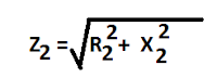
The rotor impedance/ phase in running condition is given below.
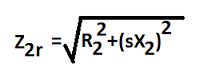
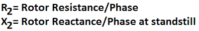
Where,
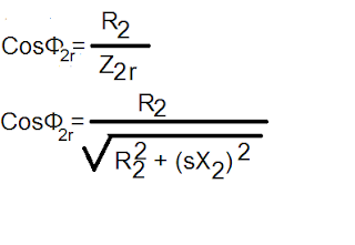
Rotor Power Factor
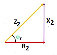
The impedance, resistance, and reactance triangle of the rotor circuit are given below.
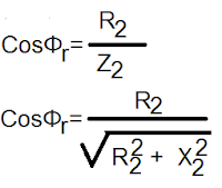
The rotor power factor at a standstill is given below.
At running conditions, the power factor of the rotor circuit is ;
Solved Examples on the slip of Induction Motor
Example 1: If the induced emf in the stator of 4 poles has a frequency of 50 Hz and that in the rotor is 1.5 Hz, at what speed is the motor running, and what is the slip of the induction motor?
fr = 50 Hz
P = 4
Ns = 120f/P
= 120 x 50/4
Ns = 1500 RPM
fr = slip x stator frequency
1.5 =s x 50
s = 1.5/50
s = 0.03
The speed of the motor
N = Ns(1 – s )
= 1500(1 – 0.03 )
= 1500 x 0.97
N = 1455 RPM
Example 2: A three-phase, 50 Hz, 4-pole slip ring induction motor has a star-connected rotor. The full load speed of the motor is 1460 rpm. The rotor resistance and stand-still reactance per phase are 0.1 ohm and 1.5 ohm, respectively. The open circuit voltage on open circuit between the slip rings is 90 volts. Determine (i) percentage slip (ii) induced emf in rotor per phase (iii) the rotor reactance per phase at full load (iv) the rotor current and full load power factor.
(i) Ns = 120f/p
= 120 x 50 /4
= 1500 rpm;
slip = (Ns – N) / Ns
= (1500 – 1460)/ 1500
= 0.0266 Percentage
slip = 2.66 %
(ii) Induced EMF per phase in the rotor at standstill = 90/√3 =51.96 Volts
Rotor-induced EMF at full load Er = sE2
= 0.0266 x 51.96
= 1.382 volts
(iii) Rotor reactance at a standstill = 1.5 Ω / phase
Rotor reactance per phase at full load = sX2
= 0.0399 Ω / phase
(iv) rotor impedance per phase at full load
Z2 = √( R22 + sX22 )
= 0.1077 Ω
Rotor current per phase = 1.382/0.1077
= 12.83 amps
Full load power factor = R2/Z2
= 0.1/ 0.1077
= 0.929
Example 3: A three-phase slip ring induction motor has a star-connected rotor. The EMF of 60 volts on an open circuit generates between the slip rings at a standstill at the rated stator voltage. The resistance and stand-still reactance of the rotor per phase are 0.5 Ω and 5 Ω, respectively.Determine the rotor current per phase
(i) when the rotor is at a standstill and connected to a star-connected rheostat of resistance 5 Ω and reactance of 0.5 Ω per phase.
(ii) when running at 4 %, slip with rheostat short-circuited.
Current through rotor at a standstill = current at starting As external resistances have a connection in the series with a rotor having resistance and reactance per phase R2 = 5.5 Ω; X2 = 5.5 Ω, respectively.
(i) I2 = E2/ √(R22 + X22 )
= (60/√ 3) / √ ((5.5)2 + (5.5)2 )
I2 = 4.454 amps
(ii) When running at 4% slip
I2 = sE2/ √(R22 + (sX22 ))
= (0.04 x 60/√ 3) / √( (0.5)2 + (0.04 x 5)2))
= 2.573 amps
Example 4: A three-phase, 12-pole, salient-pole alternator is coupled to a diesel engine running at 500 rpm. It supplies an induction motor with a full load speed of 1440 rpm. Find the percentage slip and number of poles of the induction motor.
Frequency of supply to the induction motor
f = pn/120
= 12 x 500 / 120
= 50 Hz
Speed of Induction motor = 1440 rpm,
Number of poles of induction motor = p = 120 f / n
= 120 x 50/1440
= 4.16
The number of poles is to be even, selecting the nearest even number as the number of poles p = 4
Synchronous speed of the induction motor
Ns = 120f/p
= 120 x 50 /4 = 1500 rpm
slip = (Ns – N) / Ns
= (1500 – 1440)/ 1500
= 0.04 Percentage slip = 4 %
Related Articles:
Interesting: I was at a university electrical power conference once when a 4th year student presented his findings on some aspect if induction motors, and during the question time, someone asked him about slip. His response :”Slip? What’s that?”
One wonders how he could possibly have missed this essential characteristic! But stranger things have happened!