Overfluxing in transformer is a critical condition that occurs when the voltage-to-frequency ratio (V/f) exceeds its designed limit, leading to an abnormal rise in core flux density.
When this limit is breached, the transformer core moves into a state of magnetic saturation, causing excessive eddy current losses, non-linear magnetization, and severe heating.
If not addressed, this condition can lead to insulation failure, reduced efficiency, or even permanent damage to the transformer.
In this article, we’ll delve into how a transformer works, the role of flux density in CRGO core, the impact of V/f ratio on flux, and the reasons for overfluxing.
You’ll also learn about the permissible flux limits, the effects of core saturation, and how overfluxing protection relays help safeguard transformers from long-term harm.
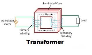
How Does the Transformer Work?
The transformer has two coils wound around a common magnetic core. When an alternating voltage is applied to the primary coil, current flows through it, producing magnetic flux.
The magnetic flux produced in the primary coil is proportional to the ratio of the applied voltage to the frequency.
According to Faraday’s law of electromagnetic induction, the EMF is induced in the primary. As per Lenz’s law, the induced EMF always opposes the primary current responsible for producing the EMF.
The following mathematical expression can express the voltage induced in the coil.
E = 4.44 Φf N
Where,
E = Induced EMF in the primary coil
Φ = The magnetic flux
f = Frequency
N = Turns /Phase
The flux travels through the magnetic core, and it gets linked to the secondary coil. Practically, all the flux produced in the primary does not link to the secondary.
Some parts of the magnetic flux link to the primary coil and other parts of the transformer. The flux that does not link to primary and secondary coils is the leakage flux. The losses in the transformer increase with an increase in the leakage flux.
The useful flux that links to the secondary coil induces a voltage in the secondary, according to Faraday’s Law of Electromagnetic Induction. The voltage induced in the secondary coil is
Es= -N dΦ/dt
The secondary voltage remains constant if the rate of change of the flux is constant. It is desirable that the flux in the transformer must remain constant.
Flux density of the CRGO Core
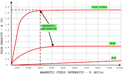
The transformer designer first checks the rated flux density of the cold rolled grain oriented (CRGO) core. The maximum flux density of the CRGO core is about 1.9 Tesla.
If the flux density of the transformer is above 1.9 Tesla, the core of the transformer gets saturated, leading to insulation failure of the laminated core.
The designed maximum flux density of the core must be below the maximum rated flux density of the core. The core must not get saturated in any case.
The magnetization curve of the different materials is given below.
The flux density of the core can be controlled during the design stage of the transformer.
It can be controlled by adjusting the cross-sectional area of the core during transformer design.
The flux through the core is the product of the flux density and the cross-sectional area of the core (Φ = B × A). The flux density of the core can be reduced by increasing the cross-sectional area of the core.
Relationship Between Flux and Voltage/Frequency
The voltage induced in the primary when the sinusoidal voltage is applied is
E=4.44 ΦfN
Φ=E/4.44f N
The Number of turns in the primary is constant for a given transformer
Φ=K* E/f
The induced voltage is approximately proportional to the applied voltage if the primary impedance is ignored.
Φ=K*V/f ———-(1)
The flux density in the core of the core is as given below.
B=Φ / A
Where A is the cross-section area of the core that is also constant.
B=K/A*V/f
B=K1*V/f ———–(2)
B ∝ V/f
Thus, the flux density in the core is directly proportional to the ratio of V/f if the number of turns of the primary is fixed.
For the on-load tap changer transformer, the number of turns is not fixed but changes according to the output voltage requirement, so we consider the flux density in the core with the tap changer, not at the center tap position.
The over-fluxing in the transformer happens with an increase in the supply voltage or a decrease in the supply frequency.
If the transformer has a tap changer and the number of turns is reduced to increase the secondary voltage, the flux density in the core will increase.
The designer always takes the margin of increase in the flux due to the tap changer operation. Also, the margin of allowable increase of voltage and decrease of frequency are considered while designing the transformer.
Causes of Overfluxing in Transformer
- The Increase of the supply voltage due to sudden load through.
- The receiving end voltage can be more than the sending end voltage due to the Ferranti effect if the line is lightly loaded.
- The transients and overshoots in the electrical network
Why Maintaining Constant Core Flux is Crucial
The rated maximum flux density of the CRGO core is 1.9 Tesla. The transformer core gets saturated if the flux density is more than 1.9 Tesla. The transformer is designed to have a flux density of 1.73 Tesla and a 10% margin in the flux density.
If the flux density in the core is below 1.9, the flux is confined in the core because the permeability of the core is more than the permeability of surrounding materials.
Effects of Core Saturation Due to Overfluxing
The flux remains confined in the core if the flux density is below the rated value. If the flux density exceeds the maximum rated value, the flux starts linking to other parts of the transformer through the air.
Beyond the saturation point, the flux density becomes constant, and the additional flux starts linking to the steel parts and induces the eddy current in the loops. The eddy current heats the structural parts and raises the temperature of the core.
The transformer’s core can get damaged if the over-fluxing is allowed for extended periods.
Moreover, if the transformer’s core is overexcited, it operates in the nonlinear region of the B-H curve. The exciting current is no longer sinusoidal and generates harmonics. The 5th-order harmonic is produced when the core of the transformer gets saturated.
The higher frequency current tends to flow at the outer surface of the winding conductor because of the skin effect. The effective area of the conductor gets reduced, and its resistance increases.
This causes higher I²R loss and additional heat loss in the winding. Also, the higher frequency current causes a temperature rise of the transformer core on account of the eddy current, as the eddy current loss is proportional to the square of the frequency.
If the transformer is operated under over-fluxing for a long time, the laminated stamping insulation is apt to fail. Therefore, the transformer must not be operated under over-fluxing.
The over-fluxing in the transformer can be judged by inspecting it during maintenance. The over-fluxing causes a temperature rise in the core, winding, and transformer parts.
The rise in temperature adversely affects the life of the transformer. The transformer oil properties change with temperature increase.
The dissolved gas analysis (DGA) must be performed once a year to check the transformer’s health. The heating causes discoloring of the tank’s paint, carbonized material in the transformer oil, discoloring of the insulation of the winding, and blistering of the paint.
Permissible Flux Density Limits in Transformer
The saturation flux density of the cold rolled grain oriented (CRGO) core is 1.9 Tesla.
As per the present design practice, the peak rated value of the flux density is kept at about 1.7 Tesla, which is about 0.9 times the rated value.
The design margin of 10% in the flux density is kept to take care of increased flux density with an increase in the system voltage or a decrease in the system frequency, and the thermal time constant of transformer heated parts.
The maximum over-fluxing in the transformer shall not exceed 110%. The transformer can continuously operate at 110% of the designed flux density.
However, the operation above 110% and up to 130% of the flux density can be allowed for a shorter period. If the flux density increases to 140%, the transformer shall be tripped instantaneously to avoid permanent damage.
The table shows the permissible over-fluxing of the transformer.
| Over Fluxing (V/f) | 1.1 | 1.2 | 1.25 | 1.3 | 1.4 |
| Duration (Minutes) | Continuous | 2 | 1 | 0.5 | 0 |
Over-Fluxing Protection in Transformer
The over-fluxing protection relay is used to trip the transformer breaker in the condition of over-fluxing.
Want to know how to safeguard your transformer from overfluxing damage?
Read: Transformer Overfluxing Protection – Relay Settings & Limits
Related Articles: