Transformer is a static piece of equipment and it has primary and secondary winding. The low voltage winding has few turns of wire wound around the core. The high voltage winding has many turns of wire wound around the low voltage winding. This scheme of winding reduces the electric stress between the core and the winding.
Additionally, the physical proximity of the LV winding to the core creates a capacitive coupling that necessitates a stable ground reference to prevent static voltage buildup.
Now that we understand the importance of transformer core grounding, let’s examine how it works and why single-point grounding is critical for transformer safety and performance.
What is Transformer Core?
The transformer core is formed with thin sheets of laminated CRGO core. The laminated sheets provide a conductive path to the magnetic field, but on the other hand, it provides electrical insulation between the sheets.
The laminated sheets have very low reluctance, and because of this, most of the flux pass through the core without leakage. The eddy current sets up in the transformer core because of the induced voltage in the core. The transformer is earthed to have a minimum resistance for fault current to pass to the ground. By grounding the core, we ensure that these parasitic voltages do not result in micro-arcing between the laminations and the grounded tank.
How does Core grounding Protects the Equipment?
In case of insulation failure of the winding, a high voltage is induced into the core. The induced high voltage causes partial discharge and, the transformer may fail. Thus, it is absolutely necessary to provide a low resistance path to the fault current so that the upstream breaker can be tripped to isolate the faulty equipment.
For equipment safety, we connect the transformer core to the ground from a single point. The fault current finds its path from core to the ground in case the core attains high potential caused by insulation failure.
Transformer Core – Problems Caused by Loss of Core Grounding
The transformer core is normally connected to ground at a single point to keep it at earth potential and prevent unwanted voltage buildup. If this core grounding connection is lost, either accidentally or during maintenance, the core can develop a high induced voltage with respect to grounded parts of the transformer.
This voltage buildup may cause arcing or sparking between the core and nearby grounded metal parts such as the tank wall or core clamps. In oil-filled transformers, such arcing generates fault gases known as “hot metal gases,” mainly Hydrogen (H2) and Acetylene (C2H2). Therefore, if these gases appear in a Dissolved Gas Analysis (DGA), a loose or missing core ground should be considered a possible cause.
Loss of transformer core grounding can also affect diagnostic test results, especially power factor and capacitance measurements. Under normal conditions, the capacitance between the low-voltage winding and the grounded core is measured directly. However, when the core ground is missing, the measurement path changes and behaves like two capacitors connected in series — one between the LV winding and the core, and another between the core and ground.
Because of this, the measured capacitance value becomes lower than normal. This reduced reading may incorrectly suggest winding insulation problems, even though the actual issue is simply the loss of the transformer core ground connection.
How to Ground the core of a Large Power Transformer?
There are two methods of transformer core grounding.
- Transformer core connection to transformer grounded tank
- Separate bushing for core grounding connection and connecting bushing to the external ground grid, which allows for testing the core-to-ground insulation resistance (Megger test) without opening the main tank or draining the oil.
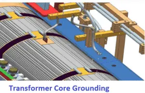
In the case of a large rating transformer, the core of the transformer has multiple sections. The cooling ducts insulate the core sections. The core jumpers bond the core sections together and the final jumpers connection connects core sections to single point earth.
The heavy magnetic field develops at the time of charging, as a result, a high voltage develops because of capacitive coupling between winding and core. The voltage developed in the core discharge through the earth point of the core. The protection device operates in the event of a winding to core insulation failure. The core of the power transformer is grounded at a single earth point in order to avoid circulating current with multiple earthing of the core.
Multipoint grounding of a transformer core can cause a serious defect because it creates a closed conductive loop through the magnetic field, leading to circulating currents and localized overheating. If a second core ground is suspected, an insulation resistance test should be performed.
A healthy transformer core insulation resistance is typically very high (often greater than 2 MΩ, depending on transformer design and test conditions), whereas a very low resistance reading may indicate an unintended multipoint ground. Such a condition requires immediate investigation to prevent overheating and possible core damage or core melting.
How to Perform Core Ground Test?
The transformer core ground test is performed by temporarily disconnecting the intentional core ground and measuring the resistance between the transformer core and tank using a digital insulation resistance tester or megohmmeter. Depending on the transformer rating, test voltages generally range from 500 V to 1000 V DC. In most cases, insulation resistance values above 2 MΩ indicate satisfactory isolation, while lower readings may suggest accidental grounding or insulation failure.
Modern insulation testing instruments provide advanced features such as automatic data recording, temperature correction, and trend monitoring. These capabilities help maintenance teams identify small insulation changes before major faults occur. When combined with diagnostic methods like Dissolved Gas Analysis (DGA) and tan delta testing, core ground measurements provide a more complete assessment of overall transformer condition and reliability.
Transformer Core – Drawbacks of Multipoint Grounding
Ideally, the transformer core should be grounded at only one location. When a core is accidentally grounded at another location (multipoint grounding), a closed electrical path is created through the core and the tank/ground.
Normal transformer time-varying magnetic flux will create eddy current flow between these multiple ground points. If this current magnitude is high, it can overheat the laminated sheet steel, potentially leading to core damage. While the negative effects of unintentional grounding via support bolts may be insignificant for small control transformers, it is a critical failure mode for large power transformers.
In cases where a second ground connection is detected but cannot be physically removed, a resistor may be inserted in series at one core-ground connection to limit this eddy current flow and prevent core heating. Note that this resistor must be removed during a Dissipation Factor (DF) test to ensure accurate measurement results.
Summary: Importance of Single-Point Transformer Core Grounding
Transformer core grounding is essential for safe operation and accurate diagnostics. The transformer core is intentionally grounded at one single point to safely discharge induced and static voltages created by electromagnetic coupling with the HV and LV windings. Maintaining only one grounding point is critical.
If the core is accidentally grounded at multiple points, a closed conductive loop is formed. The transformer’s magnetic flux induces circulating eddy currents in this loop, causing localized overheating. Over time, this can damage core insulation and, in severe cases, lead to core burning or melting. In some situations, a resistor may be installed in the grounding path to limit circulating current.
On the other hand, if the core ground becomes loose or disconnected, the core becomes electrically floating. This can create high voltage between the core and grounded metal parts, resulting in internal sparking or arcing. In oil-filled transformers, such arcing generates gases like Hydrogen (H2) and Acetylene (C2H2), which can be detected through Dissolved Gas Analysis (DGA).
A missing core ground also affects Power Factor and capacitance tests, often producing misleading results that may appear as insulation or winding defects. Therefore, transformer core grounding must always remain a strict single-point connection.
Read Next:
I’ve got good ideas from this
Thanks
Super