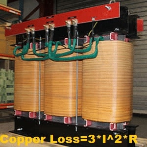
The copper loss in the transformer is equal to the I2R loss. The copper loss is very important for the calculation of the transformer efficiency. The efficiency of the transformer can be improved by minimizing the copper loss and core loss.
In this article, we will explore what causes copper loss in transformers, why it varies with load, the key factors that influence it, and the best methods to reduce copper loss and improve transformer efficiency.
What Causes Copper Loss in Transformers?
Copper loss in a transformer is primarily caused by the resistance of the winding conductors. When current flows through the primary and secondary windings, heat is generated due to the I²R effect (where I is current and R is resistance). Specifically:
- Primary copper loss = Ip² × Rp
- Secondary copper loss = Is² × Rs
Here,
- Ip and Is are the primary and secondary currents,
- Rp and Rs are the respective winding resistances..
Why Copper Loss is Called a Variable Loss?
Copper loss in a transformer occurs due to I²R losses in the primary and secondary windings, where electrical energy is dissipated as heat. This loss is directly dependent on the load because both the primary current (Ip) and secondary current (Is) increase with load.
As the transformer load increases, the current flowing through the windings also increases, which in turn increases the copper loss. Since copper loss is proportional to the square of the current (I²), it rises sharply with load variations.
Because the copper loss is not constant and changes based on the load level, it is referred to as a variable loss, unlike core loss, which remains nearly constant regardless of load.
Factors Affecting Copper Loss
Copper loss in a transformer is primarily influenced by load current and winding resistance. It is calculated using the formula I²R, where I is the RMS current and R is the resistance of the winding. Since the current varies with the transformer’s load, the copper loss is directly proportional to the square of the current.
Another critical factor is the temperature of the winding. As the load increases, the current flowing through the windings causes a temperature rise, which in turn increases the resistance of the conductor. This elevated resistance leads to additional copper loss.
In summary, the main factors affecting copper loss are:
- Load current (I): Higher load means higher current, resulting in greater I²R losses.
- Winding resistance (R): Resistance increases with temperature, further increasing losses.
- Temperature rise: Elevated operating temperatures lead to higher conductor resistance and more loss.
Understanding these factors is essential for optimizing transformer efficiency and minimizing energy wastage.
Impact of Temperature on Winding Resistance
The resistance of transformer windings—whether made of copper or aluminum—increases with temperature. As the transformer operates under load, heat is generated due to current flow, which causes the winding temperature to rise. This temperature rise leads to an increase in conductor resistance, thereby increasing copper loss.
To evaluate copper loss accurately, the resistance measured at ambient temperature must be corrected to the standard operating temperature of the transformer. For instance, if the winding resistance is measured at 30°C, it should be corrected to 75°C for an oil-immersed transformer, which is the typical rated operating temperature.
This correction is important for:
- Calculating actual copper loss under load
- Designing efficient cooling systems
- Accurate transformer performance analysis
By accounting for the temperature effect on resistance, engineers can better estimate power losses and improve overall transformer efficiency.
Temperature Correction Formula for Resistance
For copper winding, the increased value of resistance with temperature can be calculated using the following formula.
| RL=R0 [(TL+235)/(To+235)] |
Where,
RL = Resistance at TL temperature
R0 = Resistance at ambient temperature
RL = Operating temperature
T0 = Ambient temperature
For aluminum winding, the increased value of resistance with temperature can be calculated using the following formula.
| RL=R0[(TL+225)/(To+225)] |
Example: Resistance Increase Due to Temperature
Let the resistance of three HV winding of the transformer be 0.967 Ω, 0.968 Ω, and 0.967 Ω at 23.8°C.
Average resistance:
= (0.967 + 0.968 + 0.967)/3 = 0.967 Ω
Corrected resistance at 75°C:
R75 = 0.967 × [(75+235)/(23.8+235)] = 1.159 Ω
Percentage increase:
= (1.159 − 0.967)/0.967 × 100 = 19.85%
From the above calculation, it is clear that the resistance increases with an increase in temperature caused by the flow of current in a conductor.
Read Artcile on: Effect of Temperature on Resistance
Copper Loss and Transformer Loading
Example Calculations at Various Load Levels
The full load copper loss of a transformer is 1000 watts, and the copper loss at half load(50% Load) will be;
At 50% Load:
Pcu = ( % Load/100)2 x P
= ( 50/100)2 x 1000
= ( 1/2)2 x 1000
= 1/4 x 1000
Pcu = 250 Watts
Thus, the transformer’s copper loss at 50 % load is equal to 1/4 th of the full load copper loss.
At 75% Load:
Pcu = (3/4)2 x 1000 = 562.5 Watts
At 25% Load:
Pcu = (1/4)2 x 1000 = 62.5 Watts
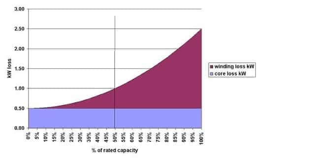
Copper loss increases rapidly with load due to its square relationship with current. This understanding is vital when operating transformers efficiently under varying load conditions.
Total Transformer Loss Formula
For a given transformer, the manufacturer can supply values for no-load loss, Pno-load, , and load loss, PLOAD.
The total transformer loss, Ptotal, at any load level can then be calculated from;
| Ptotal = Pno-load+ (% load/100)2 x PLoad |
Where,
P no- load = No- load loss ( constant loss)
% Load = load on transformer
Pload = Copper loss at rated full load
How to Measure Copper Loss in Transformer
Copper loss in a transformer can be accurately measured using the short-circuit test. This test is performed by applying a reduced voltage to the low-voltage side of the transformer while keeping the high-voltage side short-circuited. The applied voltage is just enough to circulate full-load current through the windings.
Read Article on: Open Circuit and Short Circuit Test of Transformer
How to Minimize Copper Loss in a Transformer
Reducing copper loss in a transformer is essential to improve its efficiency and performance. Copper loss occurs due to the resistance of the winding conductors, and several methods can help reduce this loss effectively.
1. Use Proper Gauge Copper Wire
One of the most effective ways to reduce copper loss is by using copper wire of an appropriate gauge for transformer windings. Thicker wires have a lower resistance, which results in less I²R loss. A conductor with a larger cross-sectional area significantly minimizes power dissipation as heat.
2. Choose High-Conductivity Copper Conductors
Transformer windings should be made of high-conductivity materials. Copper has lower resistance than aluminum, making it a better choice for minimizing copper loss. Using pure or oxygen-free copper further enhances conductivity and reduces power losses.
3. Apply Vacuum Pressure Impregnation (VPI)
Copper loss can also be minimized by using vacuum pressure impregnation. In this process, the transformer windings are placed under a vacuum, and high-pressure varnish is applied. This eliminates air gaps in the winding insulation, improving heat dissipation and lowering loss.
4. Minimize Skin and Proximity Effects in High-Frequency Transformers
In high-frequency transformers, copper loss increases due to skin and proximity effects. These effects cause current to concentrate at the surface of the conductor, effectively reducing the conductor’s cross-sectional area and increasing its resistance. Proper design techniques such as using Litz wire or foil windings help mitigate these effects and reduce copper losses.
FAQs on Copper Loss in Transformer
Copper loss in a transformer refers to the power lost due to the resistance of the winding conductors. It is calculated using the formula I²R, where I is the current and R is the resistance of the winding. This loss increases with load and appears as heat in the transformer.
Copper loss can be minimized by using conductors with lower resistance, such as thicker copper wire, and by improving insulation using vacuum pressure impregnation. For high-frequency transformers, reducing the skin and proximity effect also helps lower copper loss.
No, copper loss is not constant. It depends on the load. As the load increases, the current through the winding increases, and so does the copper loss. That’s why copper loss is also called a variable loss.
Related Articles: