Open and short circuit tests of the transformer are conducted to determine the equivalent circuit, voltage regulation, no-load losses, copper loss, and efficiency.
Transformers are among the most important electrical machines and are widely used across various applications. In power systems, for example, transformers boost the generated voltage at the power plant before transmission and again bring it down at the distribution end. The voltage is boosted during transmission to minimize heat loss and allow the transmission line to efficiently deliver bulk power over long distances. At the receiving end, the voltage is reduced to the required levels.
Transformers can efficiently perform all of this. Instrument transformers reduce current or voltage to allow small-range measurement devices to measure them accurately. Transformers are also employed in electronic devices to boost voltage and provide physical isolation between circuits.
Transformers are highly efficient electrical machines because they have no rotating parts and have two sides, primary and secondary, which are physically isolated but magnetically coupled, allowing them to transfer power from one side to the other. They do not alter the input frequency and power except for certain losses.
Therefore, if we can calculate these losses and reduce them from the input power, we can get useful power. This can then be presented as a percentage of the input power, which constitutes the efficiency of the transformer.
But how do we calculate these losses? Well, by conducting two important tests:-
- Open Circuit Test
- Short Circuit Test
These tests are not limited to the calculation of power loss. Still, they are also important for calculating different parameters in the equivalent circuit of a transformer and for voltage regulation. Let’s understand them in detail.
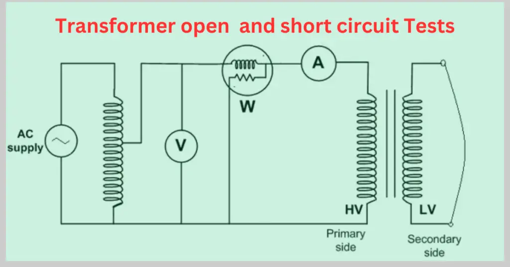
Open Circuit Test on Transformer
An open circuit test is carried out to determine the transformer’s no-load losses, which are independent of the load on the transformer. As the name suggests, the open circuit test is done by connecting the low-voltage side to the rated voltage and keeping the high-voltage side open-circuited. Thus, there is no load on the transformer to consume power, and whatever power the transformer consumes accounts for the core losses, which are hysteresis loss and eddy current loss.
The core losses are directly proportional to the supply frequency. As the frequency remains constant within the transformer, the core losses, too, remain constant, and hence, they are termed constant losses.
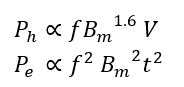
Ph and Pe are the hysteresis loss and the eddy current loss, respectively, known as the core loss. f is the supply frequency, Bm is the maximum flux density, t is the lamination thickness, and V is the supply voltage.
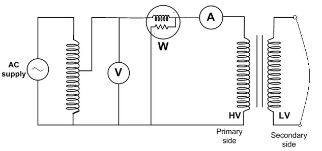
Here’s the circuit for performing the open circuit test on a single-phase transformer.
As shown in the circuit, an ammeter, a voltmeter, and a wattmeter are connected on the low-voltage side while the high-voltage side is left open-circuited. The supply voltage is gradually increased with the help of an autotransformer until the voltmeter indicates the rated voltage on the low-voltage side. At this point, the readings of the voltmeter, ammeter, and wattmeter are taken.
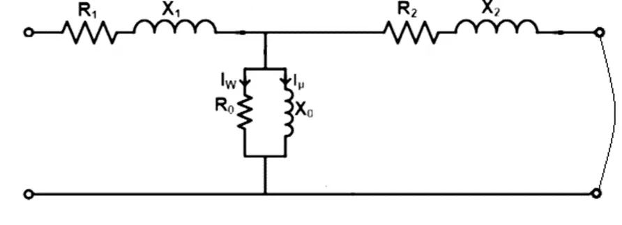
The equivalent circuit of a transformer in a general form can be represented as follows.
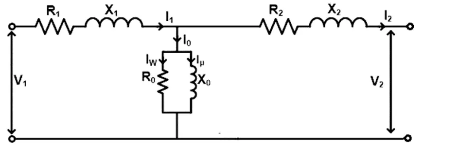
During the open circuit test, the input current is quite small, i.e., 2-6% of the full load current. This current is called the no-load current or excitation current, as shown in the figure by I0. Since the current is very small, the voltage drop across the primary leakage impedance (R1+jX1) is negligible. Also, the secondary side is open-circuited hence, there is no voltage drop across the secondary leakage impedance (R2+jX2). Thus, for all practical purposes, the circuit model for the open circuit test can be shown as the following.
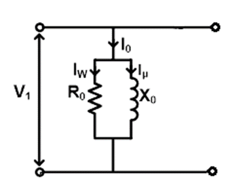
As the input current is about 2-6% of the full load current, the ohmic loss on the primary side (low voltage side in our case) is about 0.04 to 0.36% of the full load current, which can be neglected. Therefore, the wattmeter reading under no load condition can be taken as the core loss within the transformer.
Here
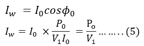
V1= Voltage reading by the voltmeter, i.e., supplied rated voltage on the low voltage side.
I0= Current reading by the ammeter, i.e., the no-load current.
Po= Power reading by the wattmeter is almost equal to the core loss within the transformer.
Therefore,
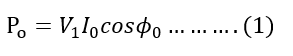
So, the no-load power factor is
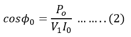
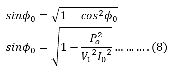
From the phasor diagram of a single-phase transformer, we get
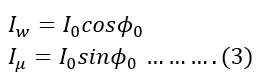
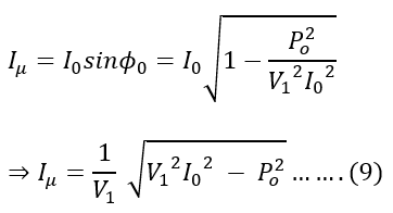
Where Iw is the current through the core loss resistance R0 and Iμ is the current through the magnetizing reactance X0.
Since we got the value of the power factor, cosΦ0 above, therefore,
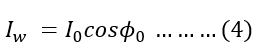
Putting the value of cosΦ0 from equation(3)in equation(4),
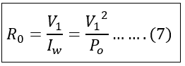
From the given circuit, we can say that
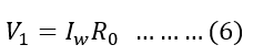
Therefore, the value of the core loss resistance can be given as,
And,
Therefore,
Again, from the given circuit, we can say that,
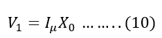
Therefore, the magnetizing reactance, X0, can be given as
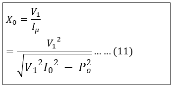
Thus, from the no-load test of the transformer, we got:-
- The core loss(Pc) at rated voltage and frequency
- Parameters like core loss resistance (R0) and magnetizing reactance (X0).
Sometimes, a voltmeter is connected at the open circuit terminal on the high-voltage side. Therefore, at the rated voltage on the low-voltage side, we can get the ratio between the voltages on each side, which gives us the turn ratio of the transformer.
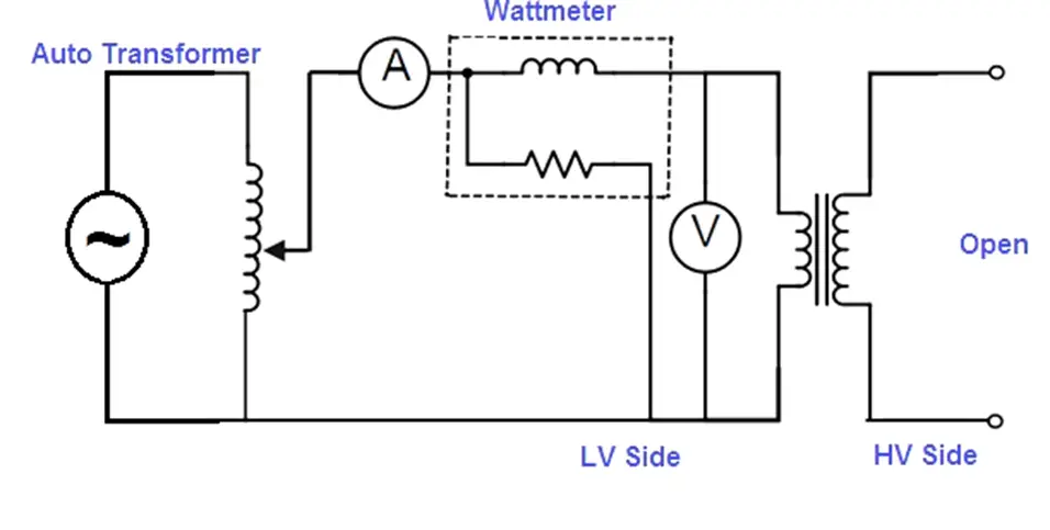
Short Circuit Test on Transformer
A short-circuit test (SC test) is performed to calculate the copper loss or the i2r loss in the transformed at full load. To carry out the short-circuit test on the transformer, the low-voltage side of the transformer is short-circuited, and measuring instruments, i.e., the voltmeter, ammeter, and wattmeter, are connected on the high-voltage side. The circuit diagram to carry out the short-circuit test is shown below.
With the help of the autotransformer, the voltage is so adjusted that the rated current flows through the primary side, i.e, the high-voltage side. As the primary mmf in a transformer is almost equal to the secondary mmf, the flow of rated current through the primary winding causes the rated current to flow through the secondary winding which has been short-circuited.
A primary voltage of 2-10% of the rated value is sufficient to cause the rated current to flow through it. As the applied voltage is small and secondary winding has been short-circuited, the exciting current i.e, the current flowing through the shunt parameters of the equivalent circuit of the transformer (i.e, R0 and X0), is negligible and hence the overall core loss is negligible as well. Hence, we can simplify the equivalent circuit by removing the shunt parameters.
After simplifying, it looks like
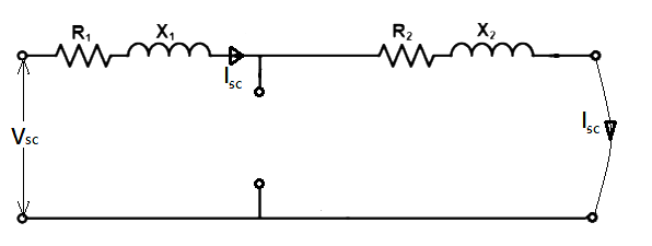
After making the connection properly and applying the rated current in the primary winding, the readings are taken from the instruments. Let Vsc and isc be the readings from the voltmeter, ammeter, and wattmeter, respectively.
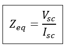
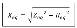
As we are dealing with the equivalent circuit, the leakage impedance on the secondary side, i.e., the low voltage side, has been referred to as the high voltage side. Thus, the equivalent leakage impedance referred to the high voltage side can be given as
Now, the equivalent resistance referred to the high voltage side can be given as
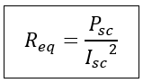
Therefore, the equivalent leakage reactance referred to the high-voltage side is
Thus, by short-circuit test of the transformer, we get
- Ohmic loss or the copper loss at rated current and rated frequency.
- The equivalent leakage resistance and the equivalent leakage reactance within the transformer.
It must be noted that the leakage impedance can also be referred to the low voltage side if required. Also, for all practical purposes, we need the value of the equivalent leakage resistance and reactance referred to any one side instead of individual values of resistances and reactances. However, if individual values are required, we can calculate them as
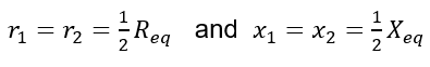
both being referred to the same side.
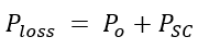
Thus, the open circuit and the short circuit tests give us the core and copper losses within the transformer. Also, we can calculate various parameters of a transformer using the values of the voltmeter, ammeter, and wattmeter employed in both tests. Thus, the total power loss within the transformer is
Hence, the efficiency of the transformer can be calculated as
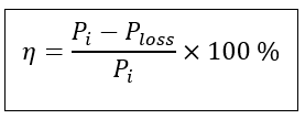
Where Pi is the total input power in the transformer.