The Power Flow Diagram of the induction motor shows the motor’s input power, losses, and the motor’s output power. The input electric power fed to the motor’s stator is converted into mechanical power at the motor’s shaft through various power stages. Here, the power flow refers to the various losses that occur during the energy conversion- from electrical energy to mechanical energy.
First, we will understand the losses in induction motors to understand the power flow diagram of induction motors.
Losses in Induction Motor
The major losses in an induction motor are as follows.
1. Fixed Losses
The magnetic flux travels through the magnetic core of the motor when the AC supply is fed to the stator. The reversal of the magnetic flux in the core causes the iron loss, which depends on the AC supply’s voltage and frequency. The voltage and frequency remain constant. Therefore, this loss is a constant loss or fixed loss.
The constant or fixed power loss occurs in the induction motor because the voltage and frequency are of two types: eddy current and hysteresis loss. The iron loss is the sum of the eddy current and hysteresis losses.
Another fixed loss in the induction motor is friction and windage loss. The induction motor is a rotating machine, and friction occurs in the roller or ball bearing of the motor and causes heat loss. The rotating machine also cuts the surrounding air; some parts of the input energy are lost in overcoming this loss is called the windage loss.
The fixed losses are independent of the load on the motor.
2. Variable losses
Variable losses, as its name suggests, depend on motor loading and, thus, vary as the load on the motor changes. When the motor powers the mechanical system, it draws current from the electric supply source. The current drawn by the motor depends on the loading of the motor.
The losses that occur in the motor because of variation in the current with loading are called copper losses because they happen in the winding of the motor. The copper loss in the motor is proportional to the square of the current and resistance of the winding(I2R). The variable or copper losses in the motor occur in the stator and rotor winding of the motor.
- Stator Copper loss
- Rotor Copper loss
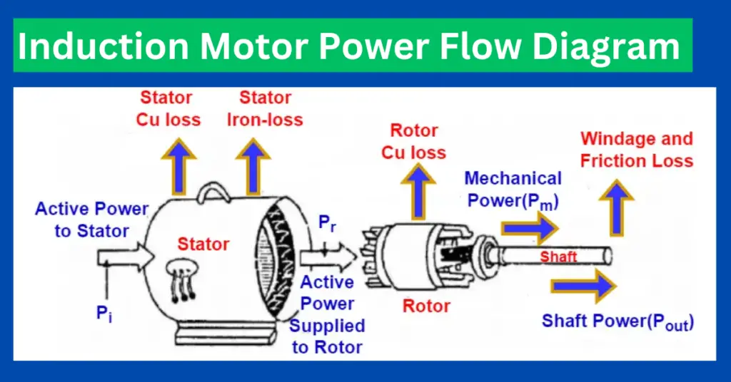
Power Flow Diagram of Induction Motor
The power stages in the induction motor are shown in the below image.
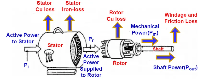
From the above diagram, it is clear that the induction motor’s output power cannot be equal to the input power. The output of the induction motor is always less than the input power because of losses like copper losses, iron losses, friction losses, windage losses, and stray losses.
Rotor Input Power
Mechanical Power
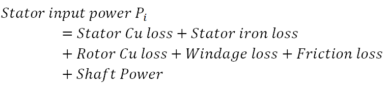
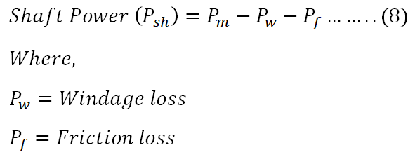
Shaft Power
Power Equation of Induction Motor
or,
Power Flow Diagram of Induction Motor in terms of Electrical Quantities
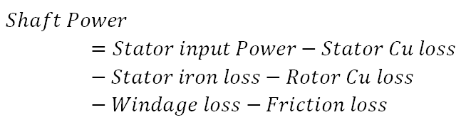
The input power drawn by the induction motor is;
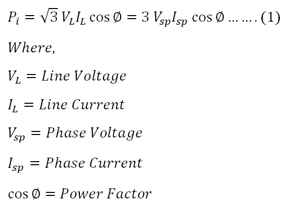
The copper loss and no-load losses occur in the stator. The no-load losses comprise eddy current and Hysteresis losses, called stator core losses. Thus, the stator core losses are;
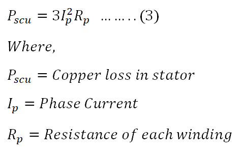
The copper loss occurs in the motor because of the heat loss in the winding. Thus, the stator copper loss in all three winding of the stator is;
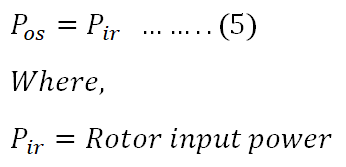
The output power of the stator is equal to the difference between the input power and losses. Thus, the output power of the stator is;

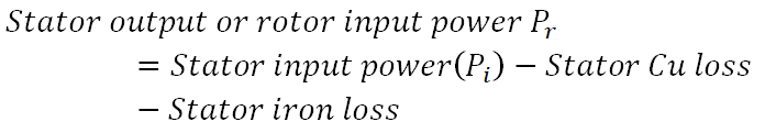
The stator output power is equal to the rotor input power.
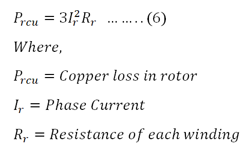
In the rotor, copper loss and core losses occur. Here, note that the iron loss in the rotor core is much less because of less rotor voltage magnitude and rotor supply frequency. Therefore, the core loss in the rotor can be neglected. Thus, the major power loss in the rotor occurs because of the copper loss. The copper loss in the rotor winding is;
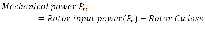
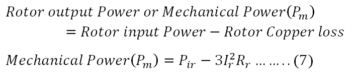
The rotor output power of the induction motor is equal to the difference between the rotor input power and losses. Thus, the rotor output power or mechanical power(Pm) is;
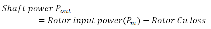
This mechanical power of the induction motor is not the actual power delivered to the load. The rotation of the motor causes friction and windage losses. The difference between mechanical power and the losses on account of windage and friction losses is called shaft power.
Related Articles: