This article describes the losses and efficiency of an alternator. An Alternator is an electromechanical machine that converts mechanical energy into electrical energy. It is comparable to a generator however alternator is the term used for a machine generating alternating current whereas generator is typically used for the machines generating DC voltage.
Like any machine or engine that converts one form of energy to another, an alternator also has various losses associated with it at various stages of energy conversion. It is always desirable that we get 100% output for the input provided(here mechanical energy using a prime-mover), but, there are various mechanical as well as electrical losses associated that cause a part of the input power to be compensated within them. Let’s understand these losses and find out the efficiency of an alternator.
Types of losses
There are various losses in an alternator:-
- Copper losses
- Core losses
- Mechanical losses
- Other losses
Copper Losses
Copper losses are the losses that happen due to the resistance of the conductors. As the stator and the rotor conductors are made up of copper, these losses are known as copper losses. Copper losses are of two types – Stator copper loss and Rotor copper loss. The stator houses the three-phase conductors while the rotor houses the field winding.
Stator winding copper loss is given as
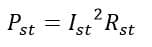
Where Ist is the stator winding current and Rst is the stator winding resistance.
Similarly, the rotor winding copper loss is given as
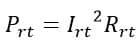
Where Irt is the rotor winding current and Rrt is the rotor winding resistance.
Copper loss is also known as i2R loss as evident from the equations above.
Core Losses
Core losses are the losses that happen due to the magnetic core of the machine. The core is the ferromagnetic material upon which winding is done. It is the magnetic circuit through which the magnetic field flux flows just like a conductor in an electrical circuit.
Core losses are also known as iron losses that occur in the pole faces, teeth, and the stator core of the alternator.
There are two types of core losses – Eddy current loss and Hysteresis loss.
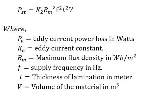
Eddy current loss
An alternator produces time-varying emf which is the result of a time-varying magnetic field within the alternator. As a result, the armature and the rotor cores are subjected to this time-varying magnetic field causing an EMF to be induced on them. This causes an eddy current to circulate on the cores and hence a loss of the input power which is called the Eddy-current loss. It is given by;
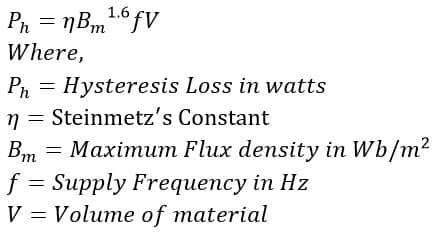
Hysteresis loss
As the magnetic field flux within an alternator is time-varying, it reverses every half-cycle. Ideally, the cores within the machine should also have their magnetic polarity reversed at the same time however that doesn’t happen. The core material retains some amount of magnetism. This causes a portion of the reversed magnetic field flux to be used for overcoming this magnetic friction. This leads to a loss of an amount of the input power as Hysteresis loss. It is given as
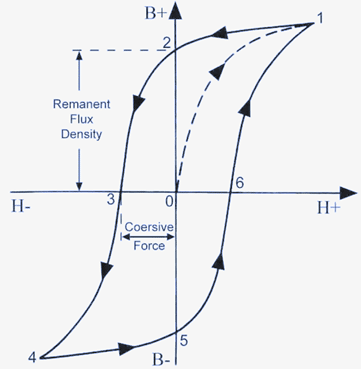
Hysteresis loss can be understood better using the B-H curve of the core material. It is shown like this
Therefore,
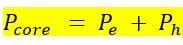
Where Pcore is the total core loss or iron loss within the machine. Core losses are also called no-load losses as unlike copper losses, core losses are not load-dependent. The minimum amount of loss happens within the machine when it is made to run even without any load connected.
Mechanical Losses
Mechanical losses happen due to the moving part of the machine i.e, the rotor. An alternator remains at standstill until and unless an external prime-mover is coupled with the machine to make it rotate. The power that is spent in changing the inertia of the rest of the machine is counted under mechanical losses.
One advantage of an alternator like any other AC machine is that the stator and the rotor aren’t in physical contact which reduces friction-related problems to a great extent and the machine is able to deliver huge amounts of power demand. There are two types of mechanical losses that are taken into account.
Friction loss
Friction loss happens due to friction in moving parts like the bearings and the coupler.
Windage loss
Windage loss is the loss of input power that happens due to the friction that happens between the rotating part (rotor) and the air around it. Windage loss reduces the effective speed of rotation of the alternator which in turn results in reduced output power.
Therefore,
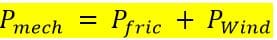
Where,
Other losses
Apart from the losses like core loss, copper loss, friction, and windage loss, there are some other losses that happen within the machine. These losses are not of very considerable amount and amount to a tiny fraction of the input power.
These losses are also called stray losses or Miscellaneous losses that happen due to magnetic field flux within the machine or due to its mechanical design.
Some of these stray losses are
- Loss due to linkage of the magnetic field with other parts of the alternator like its casing or any nearby conducting material like bearings, poles, etc.
- Ideally, the entire magnetic field flux should link with the stator conductors through the air gap. But that doesn’t happen and a part of this magnetic field flux links with other parts of the machine thus leading to a loss of the input power. This happens due to magnetic reluctance.
- Non-uniform distribution of the field flux and the generated current through the conductors.
- Loss of power generated due to wear and tear of the slip rings connected with the field winding.
Among all the losses discussed above, core and copper losses are known as internal losses as they happen within the machine whereas mechanical losses or friction-windage losses are known as external losses as they happen externally.
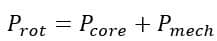
The sum of the core losses and the mechanical losses is known as the rotational losses.
All these losses result in the heating up of the machine and thus decrease the machine’s efficiency. Let’s see what is efficiency and how to calculate it.
Efficiency of an Alternator
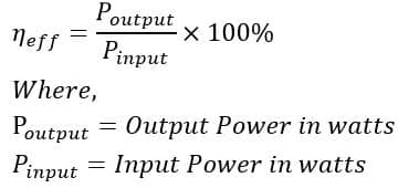
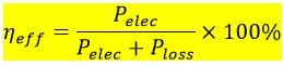
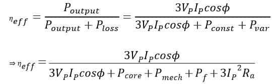
The efficiency of an alternator or any electrical machine for that matter is defined as the ratio between its output power to its input power. It is expressed in the percentage of the input power which has been converted into useful output power.
As we discussed above, a part of the input power is lost in compensating for the various losses that happen within the machine. Whatever is left after this compensation is known as the useful output power.
This output power should be as high as possible (ideally 100%). That’s why the efficiency of a good machine should be close to unity or 100%. In practical applications, a good machine has an efficiency between 85-90% or even more.
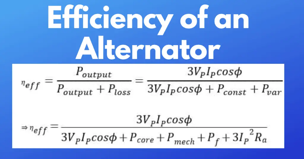
Efficiency is given as
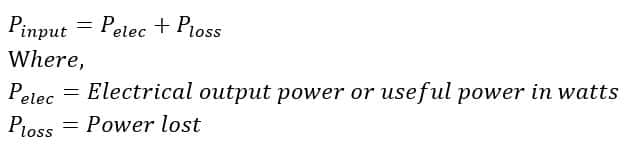
Now, the input power is converted into the useful output power and the losses. So,
Therefore, the efficiency is given as
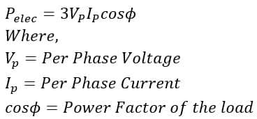
Now, an alternator in practical use has three-phase output power supplied to a lagging load. Therefore, the electrical output power can be given as
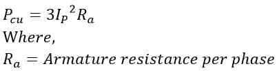
As there are three phases, the total copper loss is given as
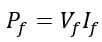
The field winding on the rotor is supplied by a DC voltage source. Therefore, the field winding loss is given by
The rotational losses are given by
Other losses or stray losses can be represented as Pstray .
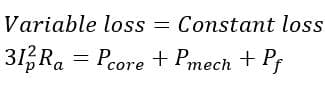
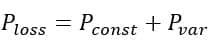
The rotational losses and the field winding loss are known as constant losses (Pconst)as these losses aren’t load dependent whereas the copper loss is known as variable loss (Pvar).
So,
Therefore the efficiency is given as
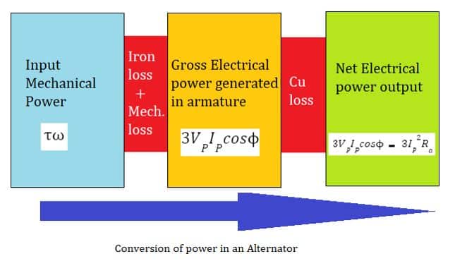
The power conversion within an alternator can be represented by the following picture.
Condition for Maximum Efficiency of Alternator
The alternator has maximum efficiency when the variable losses are equal to the constant losses of the machine.