What is DC Voltage?
DC voltage stands for Direct current voltage. It is the type of voltage that we get from batteries, DC generators, and other sources like sensors and transducers.
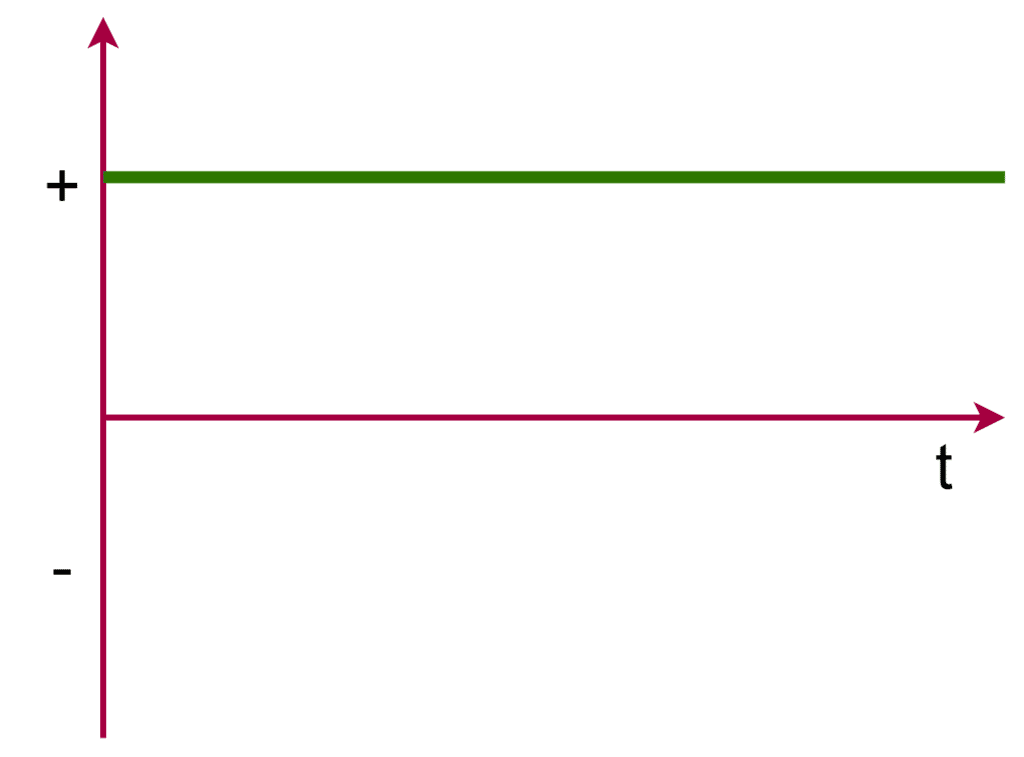
DC voltages unlike AC don’t have a frequency which means they don’t alter every half-cycle. However, in some electronic circuits, there are components that generate an alternating voltage waveform but those are called pulsating DC. This is because although these waveforms are alternating apparently, their average value in one cycle is not equal to zero.
A voltage can be called an Alternating Current(AC) Voltage if and only if it alternates every half cycle and has an average value equal to zero in one complete cycle. The average value in one cycle being equal to zero means the net voltage in a positive half cycle is equal in magnitude in the negative half cycle.
So the electrical charges flow from the source to the load in the first half cycle and from the load to the source in the negative half cycle. However, this is not the case with DC voltage. Charges flow unidirectionally from the source to the load or the circuit only. In the case of pulsating DC, there is an alternating waveform but the average value of the voltage is either positive or negative but not zero.
DC voltage is simple as compared to its AC counterpart. This is because, in the case of DC voltage, there is no concept of frequency, phase, vector, or phasor analysis. It is relatively easy to analyze mathematically and to design its components.
Today, DC voltage is largely used in small electronic components. In addition to that, DC voltage is used in industries and power plants to charge capacitors, energize field circuits, and control certain equipment. Apart from that, DC voltage bulbs and fans are used as a backup in case of a power cut.
DC voltage is ideal for charging rechargeable batteries and capacitors. AC voltage can’t be used for charging purposes. This is because of their very nature. DC voltage produces a unidirectional current that flows from the source to the circuit and hence the electrical charges simply move from the source to the charging battery or capacitor.
The capacitor acts as a storage of charge. In the case of AC voltage, the charges flow from the source to the charging component in the positive half-cycle while the opposite happens in the negative half-cycle as the component discharges back to the source. Thus, the component never charges and can rather cause a fatal accident if AC voltage is applied across its terminals.
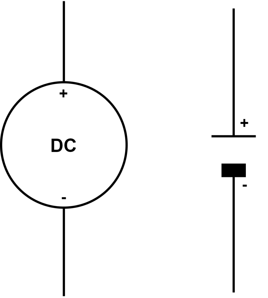
DC Voltage Symbol
The Unicode character-U+2393 “⎓” is used for the DC applications. It is also symbolled as a straight line.
IEC DC Power Circuit Wire Color Codes
IEC (International Electrotechnical Commission) provides a standard for wiring codes. The following table shows the IEC Standards for DC voltage cables.
| Function | IEC Standard | |
| Label | Color | |
| Protective earth | PE | Green-Yellow |
| Two-wire unearthed DC system | ||
| Positive | L+ | Brown |
| Negative | L- | Grey |
| Two-wire earthed DC system | ||
| Positive (Negative earthed) circuit | L+ | Brown |
| Negative (Negative earthed) circuit | M | Blue |
| Positive (Positive earthed) circuit | M | Blue |
| Negative (Positive earthed) circuit | L- | Grey |
| Three-wire earthed DC system | ||
| Positive | L+ | Brown |
| Mid-wire | M | Blue |
| Negative | L- | Grey |
US DC Power Circuit Wire Color Codes
US National Electrical code no wire color codes ungrounded system for safety reasons. The followings are the DC wire color codes for the grounded systems under the US National Electrical code
| Function | US National Electrical recommended code | |
| Label | Color | |
| Protective ground | PG | Bare, Green, or Green-Yellow |
| Two-wire ungrounded DC system | ||
| Positive | L+ | No recommendation (Red) |
| Negative | L- | No recommendation (Black) |
| Two-wire grounded DC system | ||
| Positive (Negative grounded) circuit | L+ | Red |
| Negative (Negative grounded) circuit | N | White |
| Positive (Positive grounded) circuit | N | White |
| Negative (Positive grounded) circuit | L- | Black |
| Three-wire earthed DC system | ||
| Positive | L+ | Red |
| Mid-wire | N | White |
| Negative | L- | Black |
Type of DC Sources
DC sources are the ones from which we provide DC power to an electrical or electronic circuit. These are – Voltage Sources and Current Sources.
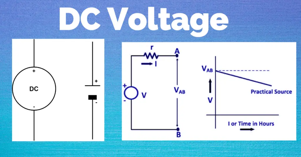
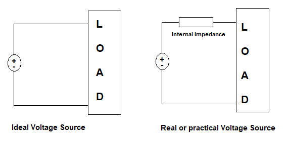
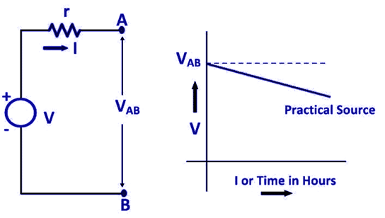
DC Voltage Sources are the ones that have constant DC voltage irrespective of the current drawn. While this is the ideal case, in the practical world, the source has some series impedance that causes the source voltage to drop as the outgoing current increases.
The voltage drop in the DC voltage source is shown below.
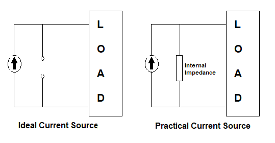
DC Current Sources, on the other hand, are the sources that provide constant DC current, irrespective of the voltage across it. An ideal current source has infinite impedance between its terminals which means it delivers the total current required to the connected circuit. While in the practical world, every current source has some impedance between its terminals in parallel to the source. Therefore, the current produced by the source is divided into two components – the load current and the internal impedance current.
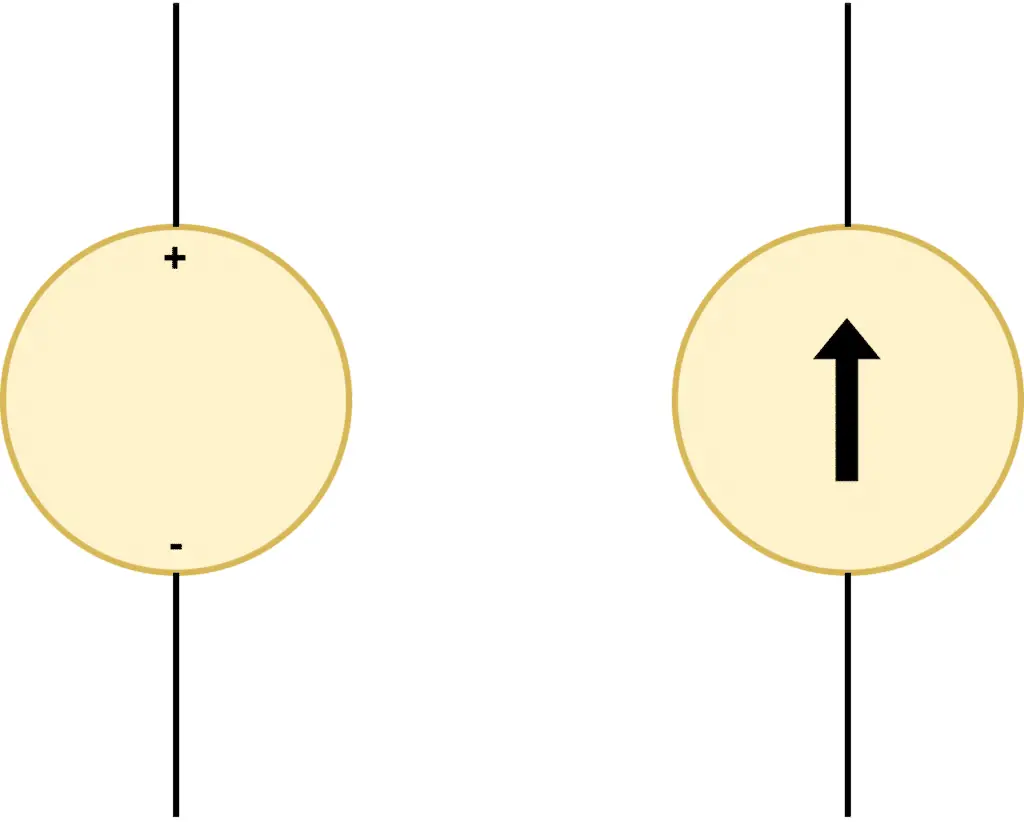
While a DC voltage source is represented by a +/- symbol (the two terminals of the battery or any other DC source), a current source is represented by an upward arrow.
Dependent and Independent DC Sources
Current and voltage sources are further sub-categorized as Dependent Sources and Independent Sources based on their nature.
An Independent Voltage source is one that generates voltage without its value depending upon the outcome of some other circuit. An example is a battery that generates voltage itself and the output value is independent of any circuit element. Similarly, independent current sources are the ones that generate current without being dependent on the output of any external circuit or element.
Dependent sources whether voltage or current, on the other hand, generate voltage or current depending upon the output of any external circuit, element, or environment. That’s why these types of sources are used to gain an electrical equivalent output of any external change or circuital change.
Sensors and Transducers are the best examples of Dependent sources. A piezoelectric sensor, for example, gives an electrical output equivalent to the pressure or weight applied to it. So, we can make use of this sensor or dependent source to get an equivalent voltage for the pressure applied. This can then be used as feedback in a control circuit.
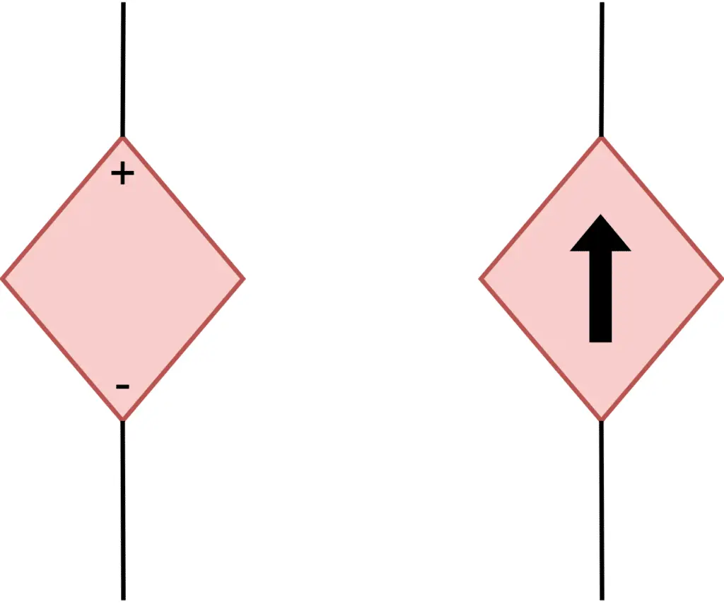
Independent sources are shown inside a circular shape whereas dependent sources are shown inside a diamond shape.
How DC is different from AC?
| DC Voltage | AC Voltage |
| The voltage generated by Generators and batteries is DC voltage | The voltage generated by alternators is AC voltage |
| DC voltage has no frequency (however pulsating DC voltage has frequency) | AC voltage has a certain frequency as it alternates every half cycle. |
| DC Voltage has no phase concept. | AC voltage value depends on time and hence there is a phase concept. |
| Two DC voltages are equal if they have the same magnitude and direction (positive or negative). | Two AC voltages can’t be said to be equal simply by looking at the magnitude. Their respective phases also must be equal. |
| DC Voltage treats an ideal inductor as short-circuit and causes maximum current to flow. This is because DC is not time-varying (except for the transient phase during the start). | AC voltage being time-variant is resisted by an inductor according to Lenz’s law of electromagnetic induction. This causes the circuit current to lag the voltage by an angle (90 degrees in the case of an ideal inductor). |
| DC voltage treats the capacitor as an open circuit. It causes the capacitor plates to charge. | AC voltage when applied across a capacitor causes the voltage waveform to lag the current waveform by an angle (90 degrees in the case of an ideal capacitor) |
| DC voltage can’t be increased or decreased using an electric transformer. | AC voltage can be increased or decreased using a transformer. |
| DC voltage has a fixed value and hence it is relatively safe to work as far as its value is concerned. | AC voltage being time-variant has a peak value that is √2 times its RMS value. Thus any insulation or safety equipment has to be made to handle the peak voltage safely. |
| DC voltage has a drop in its value only across a resistor. The drop across a resistor R is calculated as VR=IR Where I is the current passing through R. | AC voltage drops due to resistance, inductance, and capacitance in a circuit. An AC voltage drop across an impedance Z is; V= IZ=I√(R2+ω2L+1/ω2C2) Where ωL is the inductance reactance and 1/ωC is the capacitive reactance. |
| DC voltage is easy to analyze and make calculations. | AC voltage is relatively complex to work with as its value depends on time and is affected due to inductance and capacitance as well |
| Generally used in low-power applications like electronic circuits, control, and relay operations. Also used to boost the field circuit in an alternator. | Generally used for high power distribution at high voltage from the power plant to the consumers. Most of the general loads that we see around operate on AC voltage. |
| DC voltage through a circuit causes the generation of a static magnetic field that can’t link with any other circuit to gain transformer action. Thus this voltage can saturate a choke coil and burn it out. | AC voltage being time-variant in nature causes the generation of a time-varying magnetic field that can link with a secondary circuit through an air gap. This allows the transformer action to come into the picture and is advantageous in case we want physical isolation between the two circuits. This causes an increase in efficiency. |
Transmission of power using DC voltage
Thomas Alva Edison was the inventor of the DC generator. It was his idea to generate centralized DC voltage and transmit it to consumers using a transmission line.
However, this idea didn’t take off as DC power was uneconomical to transfer over long distances. This is because the generated power using DC generators had low voltages.
As we know, power is the product of Voltage and Current, the current would go up to compensate for the low DC voltage to keep the transferred power constant. The high current, therefore, required thicker transmission lines to transfer as there was a huge line voltage drop due to line resistance.
The voltage drop was so severe that it required multiple DC generators to transfer some useful power and reduce the drop. Generated DC voltage was low because there is no way that voltage can be collected from the DC generators without having physical contact with the external conductors.
This problem was solved by AC voltage. The alternating magnetic field flux causes the transformer action to come into the role and physical isolation between Primary and Secondary is possible.
Also, putting a transformer at certain distances was enough to boost the dropping voltage instead of installing multiple alternators. Generated AC voltage is boosted to a higher value thus causing the line current to reduce significantly for transferring a given amount of power.
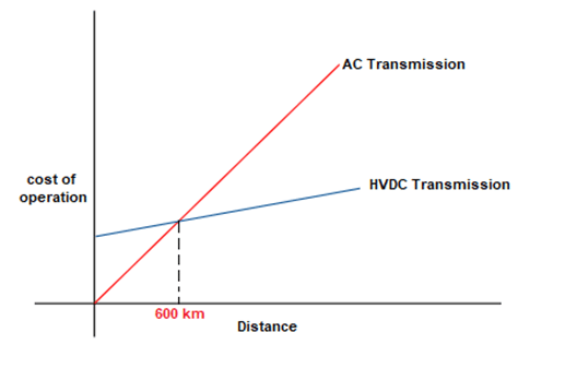
However, AC voltage causes inductance and capacitance drop. For a distance above 600 kilometers, the AC system isn’t that efficient to transfer power, and hence High Voltage Direct Current (HVDC) transmission mechanism is used. Here, the generated AC voltage is boosted using a transformer and is then converted to DC using power converters just before transmission. Before distribution, the DC voltage is converted back to AC without considerable loss of power.
Methods of Reducing DC Voltage
We need DC voltage reduction as per the application. We can reduce the DC voltage by the following methods.
- Using Resistors
- Using Diodes
Reduction of DC Voltage using Resistors
The resistors connected in the series form a voltage divider circuit. The voltage across the resistor can be obtained by proper selection of the value of resistances. A circuit diagram of the voltage divider circuit is shown below.
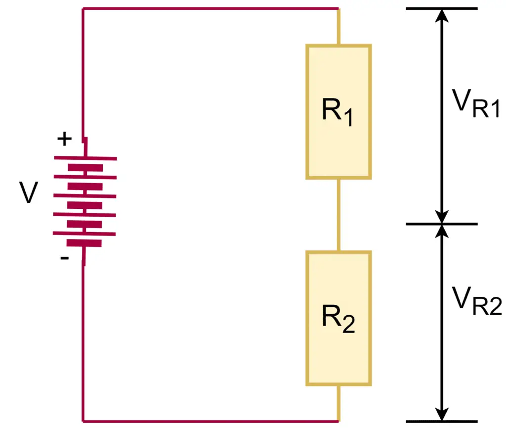
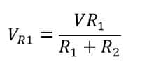
The voltage across resistance R1 is;
The voltage across resistance R2 is;
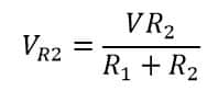
Hence, from these two equations, we can calculate the value of 𝑅1 and 𝑅2 to obtain the desired DC voltage.
Reduction of DC Voltage using Diodes
A diode conducts in the forward biasing condition and the voltage drop of 0.7 volts occurs across the PN junction. The voltage drop is about 0.6 to 0.7 V for a silicon diode and 0.25 to o.3 V for a germanium diode. The voltage drop can be increased by connecting the diodes in the series.
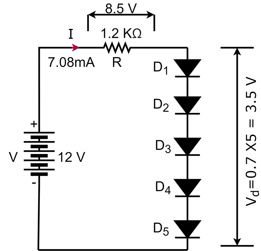
In the example shown, the voltage of a 12V battery is reduced to approximately 8.5 V, and the voltage drop across all the diodes is 3.5 V.
Reduction of DC Voltage using Buck Converter
The buck converter is an electronic converter used for reducing the DC voltage.
How to Increase DC Voltage?
The Boost converter is used to increase the DC voltage. The buck and boost converter is an electronic circuit. The boost converter has two semiconductor devices either a diode or transistor that act as a switch and one energy-storing element either a capacitor or inductor.
How to Measure DC Voltage?
We can measure the DC voltage using the-
- A DC voltmeter
- Multimeter- Keep the selection on DC voltage
- Ohm’s Law– V= IR
- Oscilloscope