Definition: HVDC transmission utilizes DC for the transmission of a large amount of power over long distances. Compared to AC transmission, HVDC (High Voltage Direct Current ) lines are more cost-effective and have lower losses. They also interconnect networks with varying frequencies and characteristics.
Everything was based on direct currents at the beginning of electrical sciences and its practical applications. One of the first applications was DC Telegraphy, which was completely powered by electrochemical batteries. DC power using dynamos was the main source of electrical lighting. At Pearl Street in New York, the first electrical station was built by Thomas Alva Edison, and it began in 1882 with an operating DC voltage of 110 volts.
In recent times, modern civilization mainly depends on the consumption of electrical energy for domestic, industrial, commercial, and agricultural applications, for which an efficient transmission system is necessary since the generating stations are in remote areas.
The requirements to make a transmission system efficient are as follows:
- Low Transmission losses
- Bulk power transmission over long distances
- Fewer voltage fluctuations
- System of interconnection
- Possibility of power transfer through submarine cables
For bulk-power transmission, UHV-AV transmission lines above 765 kV were used up to the 1980s. However, due to the development of accurate control in thyristors, the HVDC (high voltage direct current) transmission lines are being used for having a distinct superiority over UHV-AC transmission lines.
What is HVDC Transmission System?
The High Voltage Direct Current (HVDC) transmission system uses direct current to transmit power over long distances. The HVDC transmission system provides efficient and economical power transmission over very long distances that meets growing load demands. Its simple constructional feature and less complexity, research, and development make it very useful in modern power transmission.
AC is not very suitable for transmitting power over long distances, and DC is not favorable compared to AC for generating and utilizing power. Therefore, for HVDC transmission, terminal equipment is required to convert AC to DC at the sending end, and terminal equipment is again required at the receiving end to invert this DC supply obtained into AC.
Types of HVDC Transmission Systems:
The HVDC transmission systems are mainly classified into the following types based on the pole(line) arrangement and earth return. They are:
- Monopolar HVDC System
- Bipolar HVDC System
- Homopolar HVDC system
Monopolar HVDC System
HVDC system with only one pole and earth/ground return. A single conductor is required, and water or ground acts as a return path. Metallic return is used if the earth’s resistivity is high.
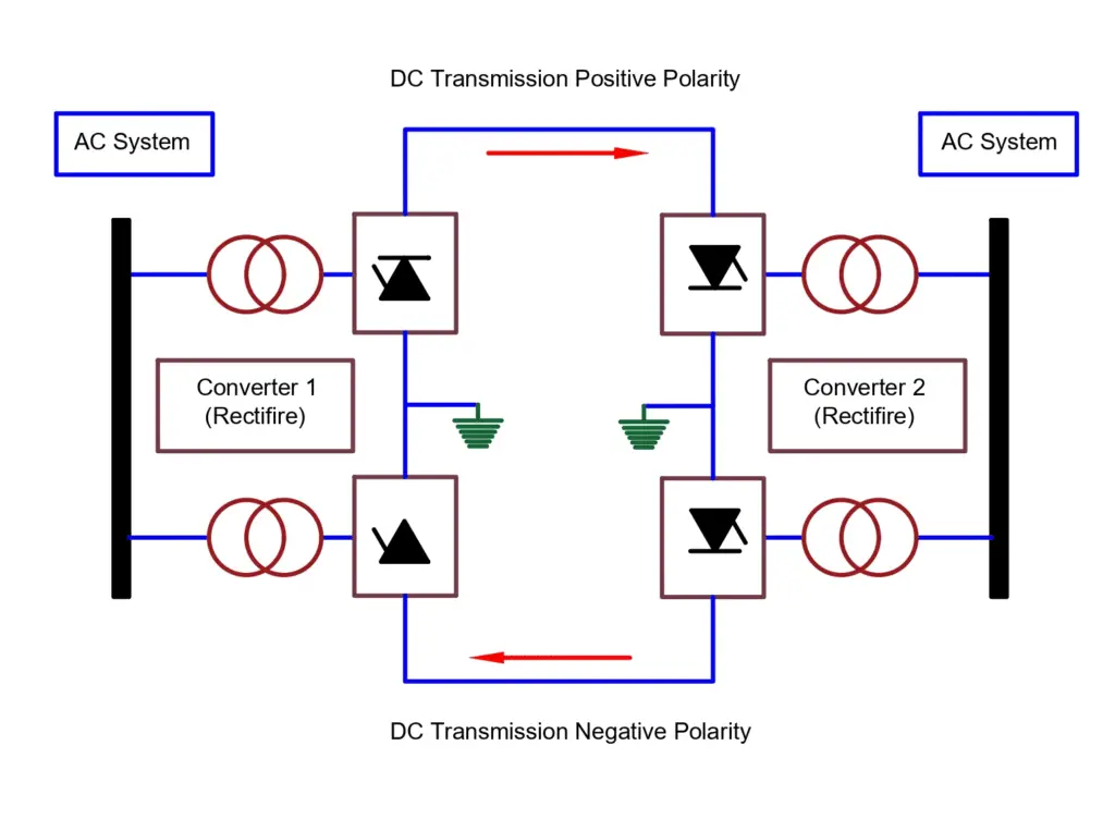
Bipolar HVDC System
An HVDC system has two poles of opposite polarity. In this, double converters of the same voltage rating are used in each terminal. The converter junctions are grounded.
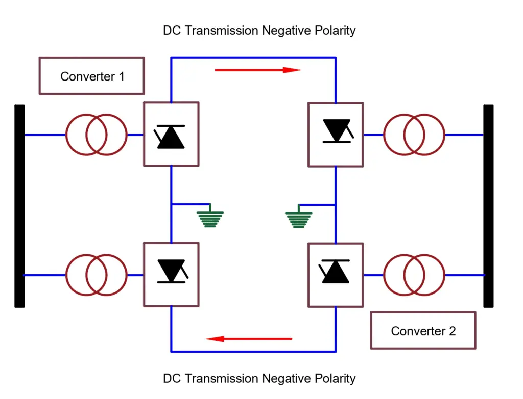
Homopolar HVDC system
HVDC System consists of two poles of the same polarity and earth/ground return path.
- Back-to-back Coupling HVDC System – No DC transmission line. A back-to-back converter takes rectification and inversion at the same substation.
- Multi-Terminal HVDC Systems – HVDC systems with three or more terminal substations.
Principle of HVDC Transmission System
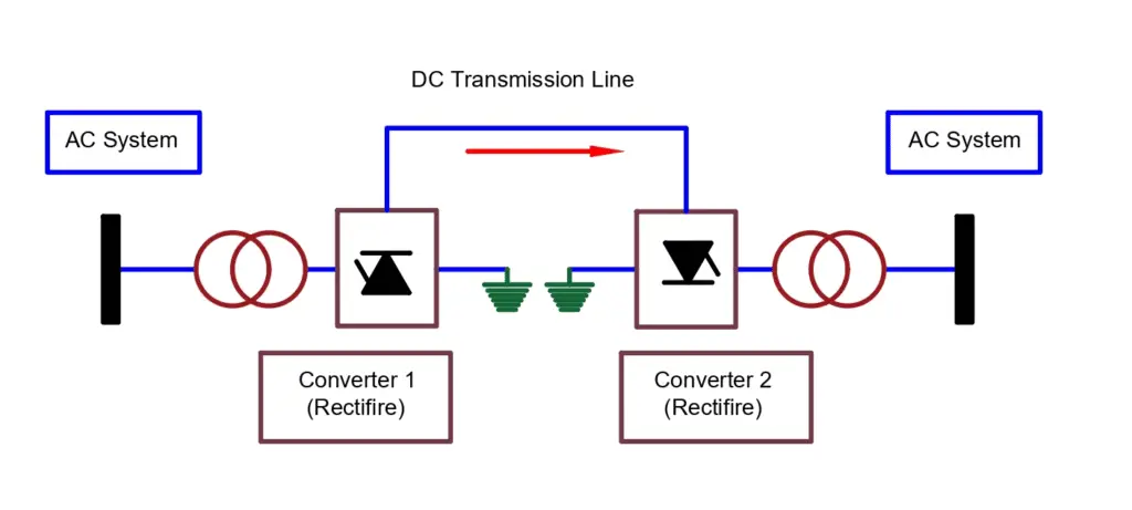
HVDC transmission system mainly consists of converter stations where conversion from AC to DC (rectifier station) is performed at the sending end, and at the receiving end, the DC power is inverted into AC power using an inverter station, therefore making the converter stations the major component of the HVDC transmission system.
With the use of a suitable converter control, we can achieve the reversal of power transfer by changing the role of the rectifier to the inverter and the inverter to the rectifier. The schematic diagram of the HVDC transmission system is as follows:
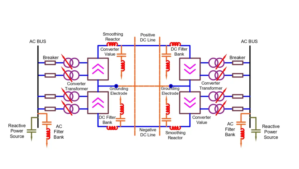
At both ends of the HVDC line, the AC substations consist of bus bars, AC switchgear, voltage transformers, current transformers, etc. For converter operation and for smoothing the DC current, smoothing reactors are necessary by reducing ripples obtained on the DC line. The midpoint of converters is connected with a distant earth electrode by the electrode line.
Advantages of HVDC Transmission
- HVDC transmission requires simple construction and reduces cost.
- The ground can be used as a return conductor.
- With the operation of DC power at unity power factor, there is no charging current.
- The power losses are reduced considerably since DC transmission has no skin effect.
- Bulk power can be transmitted over long distances.
- Power transmission is possible between unsynchronised AC distribution systems (interconnection of AC systems of different frequencies)
Disadvantages of HVDC Transmission
- We cannot use transformers to change the voltage levels.
- Requires DC circuit breakers of high cost as it is very difficult to break the DC currents.
- The cost of converting the station is increased as it requires AC &DC filters due to the generation of harmonics in converters.