In this article, we will discuss the rotor earth fault protection of alternator or synchronous generator. A synchronous generator is the main energy source and is one of the most vital parts of any power system. Therefore, it is essential to know about its steady states and various fault states that can occur during its operation.
A single ground fault on the rotor does not cause much harm as the field is operated ungrounded. However, after the first ground fault, the possibility of a second ground fault occurring because of increased voltage stress to the ground is quite dangerous, and that may cause damage to the generator.
Reasons for Generator rotor earth fault
The synchronous generator rotor winding is fairly stressed, especially in the case of turbo generators due to centrifugal forces. The rotor of the generator is an insulated DC electrical system, like a rotating part, which has a higher probability of single ground fault occurrence than the stator. The winding in the rotor is insulated from the ground but due to stresses from vibration & heat, the rotor may be earth in high-stress areas of the winding.
For the slip ring rotors, the carbon deposits on the slip rings may deteriorate the insulation resistance of the rotor. Hence, the slip rings should be checked for any deposits.
A single ground fault does not affect the rotor and the generator but it causes extra stress to the ground in the field when stator transients induce extra voltage. And, thus it increases the probability of occurrence of the second ground fault. These causes unbalance in the air gap fluxes which causes vibration and rotor-producing eccentricity.
Effect of fault on Rotor
The first rotor ground fault stresses the insulation in portions of the winding where the fault is. While the real danger is the second ground fault which can cause significant damage. The second ground fault leads to a portion of the winding being bypassed. This increased current in the remaining portion causes an unbalance in the rotor. The unbalance current causes mechanical as well as thermal stresses resulting in damage to the rotor. The mechanical stress in the form of vibrations may cause damage to bearings and even the bending of the rotor shaft. Such failures have caused extensive damage to the rotor and have also disturbed the magnetic balance of the generator.
Therefore, it is essential to detect the very first ground fault, thereby preventing a severe failure.
Rotor Earth Fault Protection Techniques
The forces resulting from the second ground fault can cause the rotor shaft to become eccentric and in extreme cases cause bearing failure. The Rotor Protection relay identifies the presence of an earth fault in the rotor winding in synchronous motors and generators. The first rotor ground fault is used for alarms while the second ground fault detection is taken for tripping of the turbine, generator breaker, and excitation system.
There are two ways to identify rotor earth faults.
By using the High Resistance/Potentiometer Technique
In this method, a resistance is connected with center tapping b/w the field winding and exciter grounded via a voltage-sensitive relay. The earth fault relay is connected between the mid-point of the high resistance potential across the field and the ground.
The disadvantage of this method is except for the center point, the relay operates for the earth faults for most of the rotor circuit but it can be adjusted by changing the tapping of the resistor, voltage will appear in the relay and gets operated.
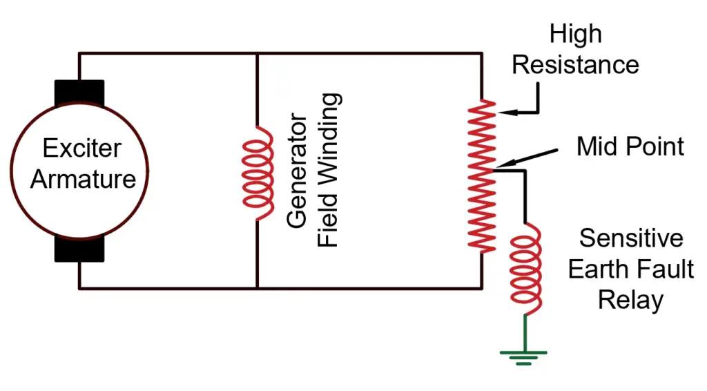
However, the probability of a second ground fault occurring is increased due to increased voltage stress to the ground which is quite dangerous.
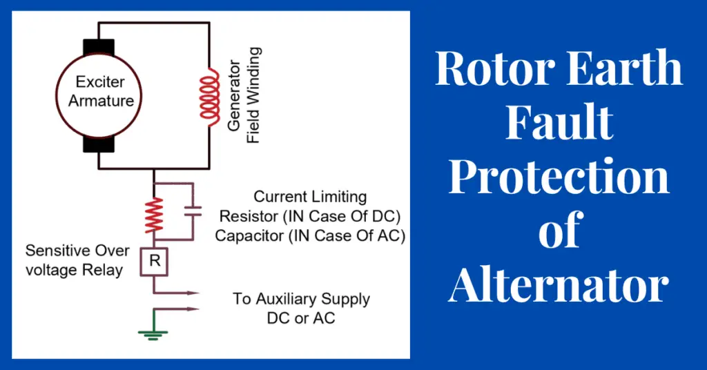
DC or the AC injection Method
The Rotor Earth Fault Protection Device consists of a current injection device that applies a DC or AC voltage to the rotor winding by means of a slip ring fitted on the rotor. The current is applied to the rotor through a current limiting resistor (In case of a DC injection) or capacitor (in case of an ac injection). In normal conditions, the system is in a floating state, the device has a high resistance, and the current flowing through the device is zero. A single earth fault in the rotor circuit completes the circuit comprising the voltage source, sensitive overvoltage relay, and the earth fault and thus the earth fault will be sensed by the relay.
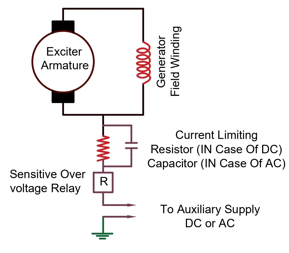
The relay can be made more sensitive in the case of DC injection as there is no issue of leakage current through capacitance as in the case of AC injection through the capacitor. For the AC injection method, the relay must not pick up on the current that normally flows through the capacitance to the ground, and care must be taken to avoid resonance between the capacitance and the relay inductance.