The measurement of insulation resistance is a key test used to check the condition of electrical insulation in equipment and wiring. By measuring how much electrical current leaks through the insulation, technicians can identify weak or damaged insulation early.
This helps prevent equipment failures and reduces the risk of electrical accidents. Performing this test regularly ensures the safety, reliability, and long life of electrical systems.
What is Insulation Resistance Test or IR Test?
The Insulation Resistance Test measures the Insulation resistance of a device under test, while phase and neutral are short-circuited together.
What is Insulation Resistance?
Ideal insulation does not allow an electric current to flow through it. The atoms within an insulating material are tightly bound to one another. Hence, it is difficult to release electrons from the material, and in normal condition, no current flow through the insulator.
The current through ideal insulation is almost nil for a particular voltage. If the voltage is increased above the dielectric strength or above the breakdown voltage of the insulator, the current starts flowing through the insulator. The insulator is said to be in a state of breakdown.
The various insulators have different breakdown voltages, and for different system voltages, various types of insulators are used.
IR Test is the oldest and most widely used test for measuring insulation resistance. The Insulation Resistance Test measures the Insulation resistance of a device under test. In the IR test, the phase and neutral are short-circuited together. The measured IR value must be higher than the specified IR value as per the standard,
The insulation resistance of the material is not perfect. When voltage is applied, some current starts flowing through the specimen. The current is called the leakage current. The IR value must be as high as possible to get a low leakage current. The lower the leakage current, the higher the IR value.
Now, let us understand why the IR test is important and what its significance is.
Why Insulation Resistance Test is done?
Measurement of insulation resistance is very important for ensuring the healthiness of the electrical system. The quality of the insulation is of prime importance for the reliable operation of electrical equipment.
We carry out the Insulation Resistance Test to ensure the healthiness of the insulation. The higher insulation is an indication of a reliable electrical system. The Insulation Resistance Tester is used to measure the insulation resistance value. The higher insulation resistance is always desirable for electrical systems.
The value of the insulation resistance deteriorates with aging and temperature. The insulation is apt to fail with a rise in temperature above permissible limits, and the insulation resistance decreases by half with every rise in 100C temperature. The insulation deterioration has to be monitored for early action before insulation breakdown.
To judge the quality of the insulation, we carry out tests like the Insulation Resistance Test(IR Test), Dielectric Absorption Ratio (DAR)Test, and Polarization Index(PI) test. In case of variation of insulation resistance from permissible value, we must take necessary preventive action well in advance.
Factors Responsible for Insulation Quality Deterioration
The quality of insulation deteriorates if the surface of the insulator traps moisture on its surface or if the surface has dirt. The insulation resistance lowers in harsh installation environments, with temperature extremes and, or chemical contamination. All these cause deterioration of insulation resistance.
- Electrical stresses: Over-voltage and under-voltage cause stress on the insulation system.
- Mechanical stresses: Frequent start-up and shutdown sequences cause high current to flow through the conductor. The high current causes heating of the conductor and lowers the insulation resistance.
- Chemical stresses: The proximity of chemicals like oils, corrosive vapors, and dust affects the insulation performance of the materials.
- Stresses linked to temperature variations: The frequent starts and stops lead to an increase in temperature because of increased current above the conductor’s rated full load current. The temperature variation lowers the insulation resistance.
- Environmental contamination causes aging acceleration of insulation.
Regular cleaning is the prerequisite for the reliable operation of the insulator.
Another important fact about insulators is that they have a negative temperature coefficient. The resistance value of the insulator decreases with an increase in temperature. The rise in temperature of an electrical machine, bus bar temperature, or electric panel temperature leads to the failure of the insulator.
We need to isolate the equipment if the temperature rise is above the permissible limit. For example, if the motor trips with a high winding temperature, we should not start the motor again and wait for some time till the temperature drops down to the permissible limit.
The conductor has insulation around it.
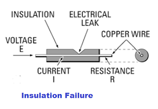
The failure of the insulation causes a short circuit, and it may cause fire hazards and electric shock as well. Therefore, it is a must to ensure the healthiness of the insulation.
Methods of Measuring Insulation Resistance
The insulation tester or Megger is the instrument by which we can measure the insulation resistance. We use the following instruments for insulation resistance measurement.
- Direct indicating ohm meter with hand-operated DC generator
- With Direct indicating ohm meter with motor operated DC generator
- Direct indicating ohm meter with DC battery
- Direct indicating ohm meter with a full-wave rectifier
- Resistance bridge circuit with galvanometer and battery
We use DC voltage to measure the insulation resistance. We can generate the DC voltage with a hand-driven DC generator or motorized DC generator. Insulation acts as a capacitor. The capacitor blocks the DC if the insulation quality is good. If leakage current flows through the insulation, it indicates the poor quality of insulation.
The insulation tester generates DC voltage, and we can select the magnitude of the DC voltage according to the insulation system’s voltage. The current flowing through the insulation indicates whether the insulation is good or bad.
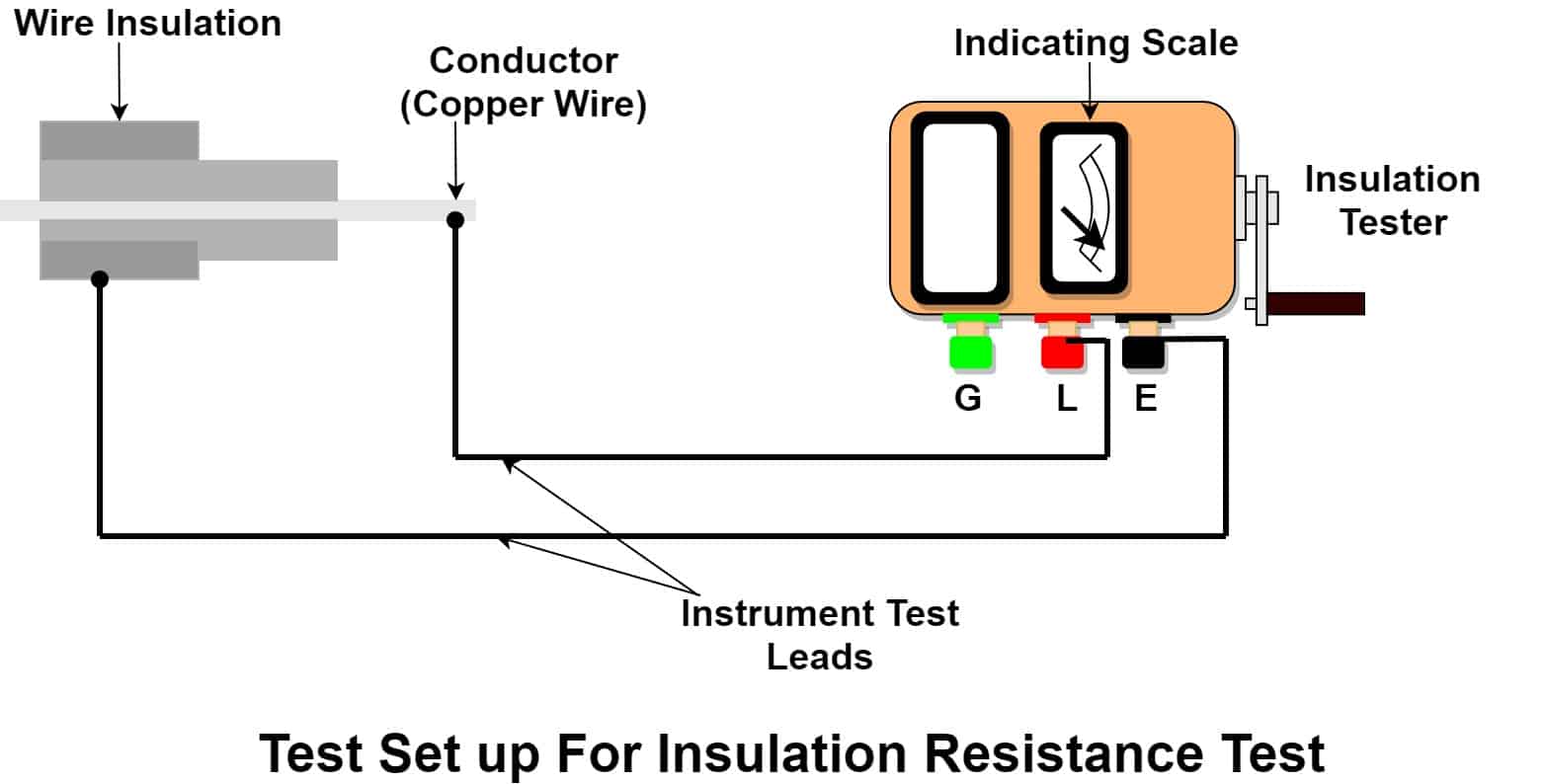
We connect the positive lead marked as L on the insulation tester to the conductor and the negative lead marked as E to the insulator surface. Thus, the DC voltage is applied across the conductor’s conductive and earth parts. Let the voltage be V and the current flowing through the insulator is I.
Insulation Resistance Formula and Calculation
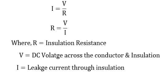
The insulation resistance formula is derived from Ohm’s Law as R=V/I, where voltage (V) is applied across the insulation, and current (I) is the leakage current measured during the insulation resistance test.
The ir test formula is given below.
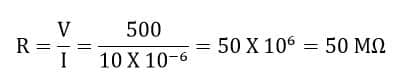
If the applied voltage is 500 volts and the current through the resistance is 10 Micro-ampere then insulation resistance is;
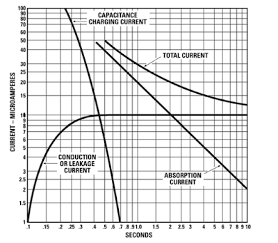
When we apply constant DC voltage across the conductor and insulator, the current drawn is the sum of the three current elements.
- Charging current,
- Absorption current and
- Leakage current.
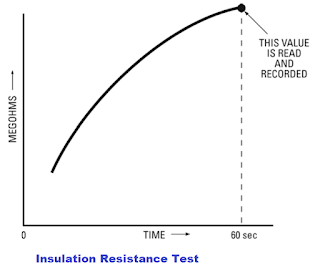
Initially, the charging and absorption current is high, and it decays very fast. The insulation tester reads insulation resistance low at the start because the charging current is high.
Taking the IR test value just after applying DC voltage does not give an accurate IR Value. Therefore, we should apply the constant DC voltage for at least one minute for the insulation resistance test.
When we apply DC voltage for one or less than one minute, the test results may not be accurate, but they reasonably indicate the insulation condition. The test is known as a short-time or spot-reading test.
How to Perform Insulation Resistance Test: Step-by-Step Procedure
Performing the Insulation Resistance Test (IR Test) correctly is essential to accurately assess the insulation condition of electrical equipment. Follow these steps for a safe and effective test:
- Prepare the Equipment
Ensure the equipment under test is disconnected from the power supply and properly isolated. Remove any connected loads to avoid false readings. - Discharge Stored Charges
Before testing, discharge any stored electrical charge by grounding the equipment terminals to prevent electric shock or damage. - Set Up the Insulation Tester (Megger)
Select the appropriate test voltage on the insulation tester according to the equipment’s rated voltage. Common voltages used are 500 V, 1000 V, or higher for industrial equipment. - Connect Test Leads Correctly
Connect the positive lead (marked L) of the insulation tester to the conductor or winding under test. Connect the negative lead (marked E) to the equipment frame or earth. - Perform the Test
Apply the DC test voltage by pressing the test button on the insulation tester. Maintain the voltage steadily for at least one minute to obtain an accurate reading. - Record the Insulation Resistance Value
Observe the insulation resistance reading on the tester display. Take note of the reading after the voltage has been applied for one minute to allow charging and absorption currents to settle. - Repeat if Necessary
For better analysis, take multiple readings at different times (e.g., after 30 seconds and 60 seconds) to calculate Dielectric Absorption Ratio (DAR) or Polarization Index (PI). - Discharge After Testing
After completing the test, safely discharge the equipment terminals again to remove any stored charge before handling. - Analyze Results
Compare the insulation resistance values with standard limits (e.g., the one mega-ohm rule). Lower values may indicate insulation deterioration or faults requiring maintenance. - Document Findings
Record all readings, test conditions, and observations for future reference and trend analysis.
Safety Precautions After Insulation Resistance Test
During the IR test, there is charge accumulation between the conductor & insulation. If we touch the conductor after the IR test, the stored charge finds its path through the human body, which may cause an electric shock. Therefore, the stored charge energy must be discharged after the IR test by connecting the conductor to the earth’s potential.
What is the allowable lower limit for Insulation Resistance?
The one-mega ohm rule establishes the allowable lower limit of insulation resistance. The one mega-ohm rule states that there will be approximately one megaohm resistance for every 1000 volts of operating voltage.
If the equipment is rated for 6600 Volts, the minimum insulation resistance value should be 6600/1000=6.6 Mega-Ohm.
Limitations of the Insulation Resistance (IR) Test
The insulation resistance changes with temperature and humidity. Therefore, the spot reading of IR does not give the correct insulation resistance value.
Time Considerations in Insulation Resistance Test: Spot Reading vs. Time Resistance Test
The spot reading or short-time reading of the insulation test does not give a clear picture of the insulation quality. The double reading test or time resistance test, like the DAR and PI tests, gives a clearer picture of the insulation condition.
Other factors like temperature and humidity do not affect the results of the insulation resistance measurement in the time resistance test. Therefore, the time resistance test or the double reading test is the best method for checking the insulation resistance.
Dielectric Absorption Ratio (DAR) and Polarization Index (PI) Tests Explained
In the DAR test, we take the insulation resistance reading after 30 seconds and 60 seconds. The 60-second IR value reading is divided by the 30-second IR value reading, and the ratio of the 60-second IR reading to the 30-second IR reading is the DAR of insulation. If we divide the 10-minute IR reading by the 1-minute IR reading, the ratio is the polarization Index of insulation.
Read detailed article on: Polarization Index(PI) Test and DA Test
Insulation Resistance Test Voltage Selection Based on Equipment Voltage Rating
The commonly used DC test voltage for routine maintenance is as follows.
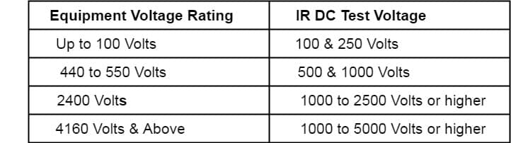
The test voltage of the first manufactured equipment is somewhat higher than the routine maintenance test voltage.
Conclusion
The measurement of insulation resistance plays a vital role in maintaining the safety and reliability of electrical systems. Regular and accurate measurement helps detect early signs of insulation deterioration, preventing unexpected equipment failures and electrical hazards.
By following proper testing methods and safety guidelines, maintenance teams can ensure the insulation remains effective over time, thereby extending the lifespan of electrical equipment and minimizing downtime.
Consistent monitoring through the measurement of insulation resistance is essential for a proactive maintenance strategy and safe electrical operation.
Related Articles:
Very usefull information as it is the basic parameter to check healthiness of every electrical equipment
Thank you sir