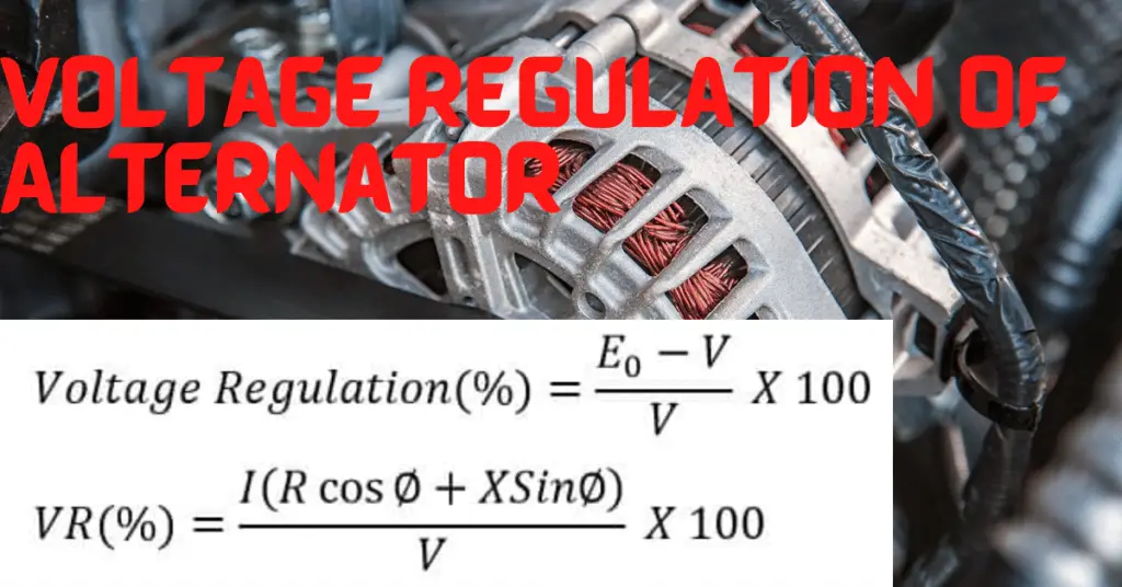
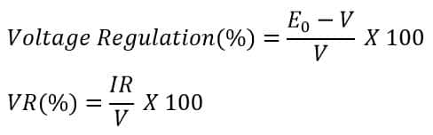
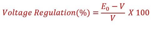
The voltage regulation of an alternator or synchronous generator is defined as the change in the terminal voltage of the generator on the application of load when the speed and the field current(excitation) remain constant.
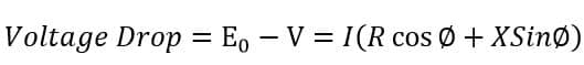
When the generator is at no load, the terminal voltage will be more, it is equal to induced EMF in the armature. The fact is that the terminal voltage does not remain constant on increasing load on the generator. The terminal voltage decreases with an increase in load. Also, the armature current increase with an increase in load. And, this increase in armature current causes a voltage drop in the induced EMF because of the armature reaction and voltage drop in the resistance and reactance of the alternator..
When the generator is at no load, the armature current becomes zero and the armature reaction does not happen. Thus, in this condition, the terminal voltage is equal to the induced EMF.
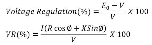
The voltage regulation shows the degree of variation in the terminal voltage of the generator with increased loading. In other words, the change in the terminal voltage from no-load to rated full load divided by full load rated voltage is called voltage regulation of the alternator.
Formula of Voltage Regulation of Alternator
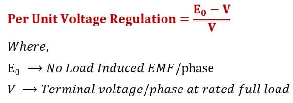
Per Unit Voltage Regulation Formula:
Per unit voltage regulation of the alternator is given below.
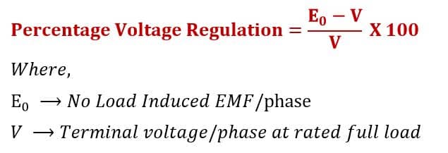
Percentage Voltage Regulation Formula:
The percentage voltage regulation formula is given below,
It is desirable to have the voltage regulation as much smaller as possible because a higher value of voltage regulation causes lower efficiency and the deterioration of the machine’s performance. The ideal generator has zero voltage regulation. However, it is not possible to design an ideal alternator.
How does the regulation depend on the load power factor?
The generator delivers the power to electrical loads, resistive, inductive, and capacitive. The type of load may be a combination of resistive, inductive, and capacitive types. The power factor of the pure resistive load is unity. On the other hand, the power factor of inductive load and capacitive load is lagging and leading respectively.
Generally, an alternator delivers power to the load that is inductive in nature. And, you will find that the power factor is 0.8 to 0.85(lag) engraved into the nameplate of the generator.
Alternator Operating at unity Power Factor
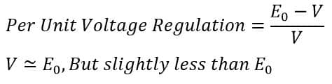
When a generator operates at a unity power factor, the voltage drop takes place in the armature resistance only. Therefore, the terminal voltage is slightly less than the induced EMF of the generator.
The voltage regulation at the unity power factor is;
Thus, an alternator has a small positive voltage regulation when it operates at a unity power factor.
Alternator Operating at lagging Power Factor
When the generator operates at a lagging power factor, the voltage drop takes place in both armature resistance and armature reactance. The voltage drop in the alternator when operating at a lagging power factor is;
The voltage regulation of alternator at lagging load is;
Thus, the more voltage drop causes a large positive regulation.
Alternator Operating at lading Power Factor
When an alternator operates at the leading power factor, its terminal voltage becomes more than the induced EMF. The Voltage regulation of an alternator at the leading power factor can be expressed as;
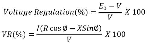
The terminal voltage rises with an increase of load at leading power factors. Therefore, the voltage regulation is negative.
At certain leading power factors, the terminal voltage may become equal to the induced EMF.
Determination of Voltage Regulation
There are many methods for determining of voltage regulation of an alternator. We will discuss here two methods for the determination of voltage regulation.
- Direct loading method
- Indirect method
Direct Loading Method
This method is suitable for determining the voltage rating of the small rating alternators. The connection diagram of an alternator is given below.
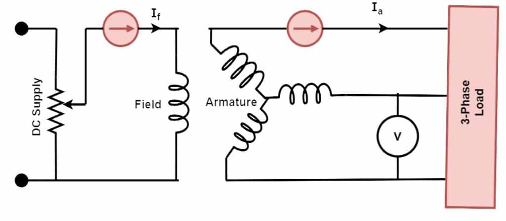
Steps of direct Loading Method
- The field current(If) is adjusted until the voltmeter connected across the armature terminal reads the rated voltage(V).
- Now, connect the 3-phase load to the armature and vary the load until the ammeter reads full load current.
- The terminal voltage decrease after performing step no. 2, therefore adjust the terminal voltage by governing the field current until the voltage reads the rated voltage(V).
- Now, keep the same exciting current and step as of step no. 3 and remove the load.
- After removing the load record the terminal voltage. Here, the terminal voltage(V) is equal to the induced EMF(E0).
After recording V and E0, we can determine the voltage regulation of an alternator using the following formula.
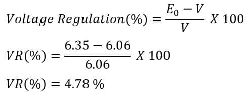
Solved problem on voltage regulation by direct Loading Method
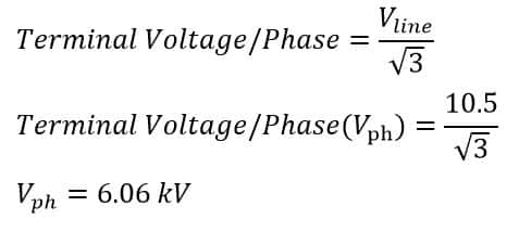
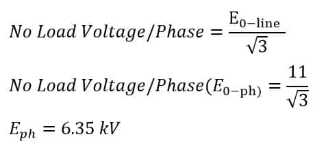
The terminal voltage(line voltage) of a 3-phase star-connected alternator is 10.5 kV at a 0.8 lagging power factor when the alternator is fully loaded. After disconnecting the load, keeping the same speed and excitation, the voltage rise to 11kV. Calculate the voltage regulation.
Given data-
terminal Voltage(line)= 10.5 kV
No-load voltage(Line)= 11 kV
The terminal voltage/phase of the alternator is;
The induced EMF or no-load voltage/phase of the alternator is;
The voltage regulation of the alternator is;
Indirect Methods of Voltage Regulation
The voltage regulation of the large rating alternators can not be determined using the direct method. The indirect method simulates the load conditions and determines the voltage regulation. The following indirect methods are used to determine the voltage regulation.
- Synchronous impedance method or EMF method
- Zero power factor method or Potier triangle method
- Ampere-turn method or MMF method
- ASA Modification of M.M.F. Method