An overcurrent relay is a protective device that is used to trip or open a circuit when the current flowing through it exceeds the threshold limit set by the relay. These relays are known for their speedy operation during a fault and are hence used widely in high-voltage applications. Let’s know in detail about the working of an overcurrent relay.
Types of Overcurrent Relays based on their Application
Overcurrent relays are widely used in different applications. Each application requires protection against overcurrent in different ways. Here’s a list of different types of overcurrent relays and their application
| Overload protection | Thermal Relays |
| Low-voltage distribution system | HRC Fuse, drop-out fuse |
| Instantaneous Overcurrent protection | Moving Iron type, Moving coil type, attracted armature type |
| Inverse time characteristics | Electromagnetic Induction Relay, PMMC type or Static Relay |
| Directional overcurrent protection | Induction relay with directional feature |
Classification of Overcurrent Relays based on Time of Operation
Overcurrent relays can be broadly classified into the following categories based on their respective time of operation
- Instantaneous overcurrent relay
- Definite time overcurrent relay
- Inverse time overcurrent relay
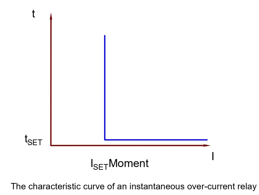
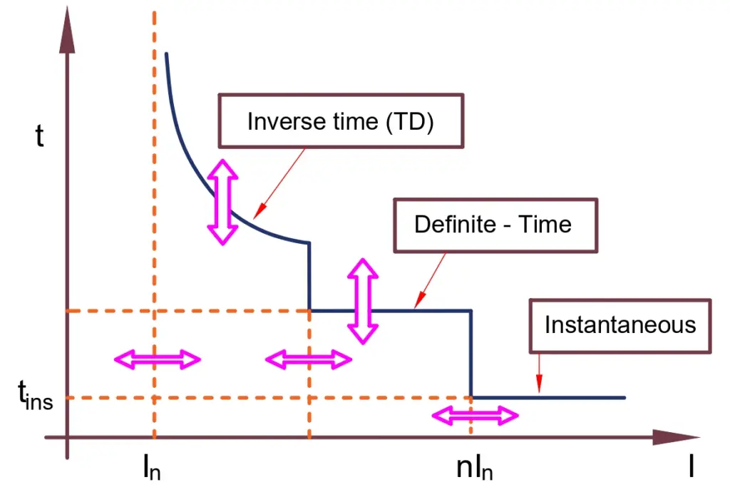
Instantaneous Overcurrent relay
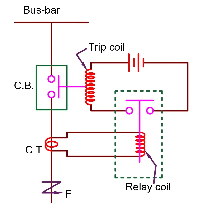
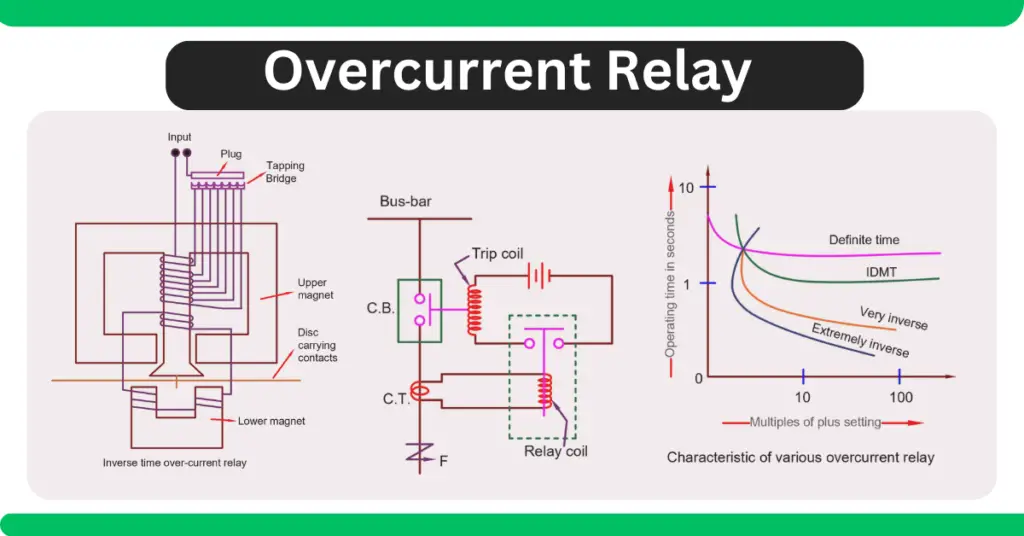
The above-given picture is a representation of the working of an instantaneous overcurrent relay. As the name suggests, an instantaneous overcurrent relay trips off the circuit as soon as a current higher than the set threshold is sensed by it.
This relay has a relay coil that carries current from the current transformer which is connected to the main circuit or bus bar. The current transformer reduces the amount of current through the line which can be safely handled by the relay.
Under normal working conditions, the current through the CT which goes into the relay coil is such that the magnetic field produced by the coil isn’t enough to attract the handle which goes through the relay coil. The handle is restrained by a control spring whose force is higher than the attraction force of the relay coil electromagnet.
As soon as the current in the main bus bar rises beyond the set threshold, the current transformer sends a higher current to the relay coil. This current causes the relay coil to energize highly enough to attract the handle. As it is clear from the image above, the handle causes the circuit of the trip coil to complete which is connected to a battery. The trip coil thus breaks the circuit and avoids any overcurrent situation.
The threshold limit of current can be set by the Plug Setting Multiplier (PSM) of the relay which is a multiplier of the full-load current of the circuit. These relays work instantly without any intentional delay (except the physical limitations) and hence these are called instantaneous relays.
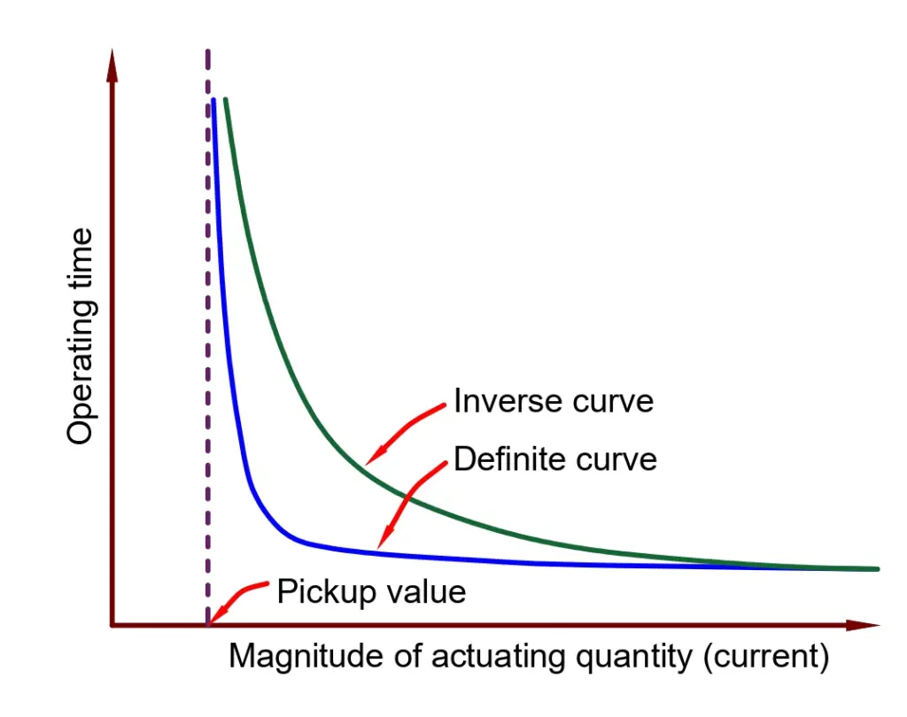
Definite Time Overcurrent Relay
A definite time overcurrent relay comes into action after an intentional time delay. Unlike the instantaneous overcurrent relay which causes the circuit to trip-open immediately in case of an overcurrent situation, a definite-time overcurrent relay allows the overcurrent or the overload to sustain for a certain period of threshold time.
This threshold time delay can be set using Time Multiplier Setting (TMS). After this time delay, if the current flowing through the circuit is higher than the one set by Plug Setting Multiplier(PSM), the relay causes the circuit to trip open and avoid the fault to spread across the power system.
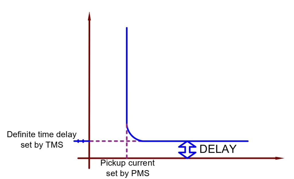
The intentional delay that the definite-time overcurrent relay introduces, allows the circuit to operate under overcurrent for a certain duration of time. This is required when the line is expected to carry overcurrent for a certain amount of time which may not be because of fault but due to a change in load over time.
An instantaneous relay will trip open the circuit immediately, disallowing any overload while a definite-time overcurrent relay takes the amount of time into account along with the amount of the overcurrent to decide whether it is a sustained overload or not.
Inverse Time Overcurrent relay
These types of relays are widely used in high-voltage operations. The time of operation of such relays is inversely proportional to the amount of overcurrent. It means that the higher the value of input current, the smaller the amount of time that the relay takes to come into action and hence ensures speedy protection of sensitive and costly power system devices.
An Inverse time overcurrent relay is an induction-type rotating relay. The current passing to the system is made to pass through the relay. The relay coils cause an induction disc to rotate due to the electromagnetic forces generated by the current passing through the relay.
Under normal situations, the disc remains at a standstill position. But when an overcurrent is sensed by the relay, the disc starts rotating. The speed of rotation of the induction disc is directly proportional to the amount of current passing through the relay.
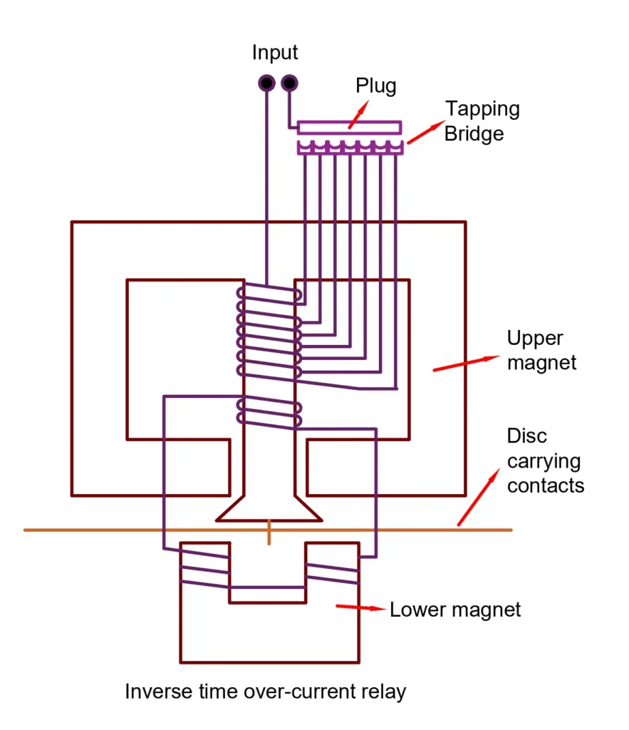
The induction disc carries a contact point. During an overcurrent situation, the disc rotates and closes the contacts of the circuit breaker. As a result, the circuit breaker immediately trips open the circuit and protects the system from the overcurrent fault.
If the delay time is set to zero, a definite-time relay works like that of an instantaneous relay.
The advantage of such relays is that they are reliable in places where speedy operation is sought to protect the system from surges. The inverse-time characteristic ensures protection at a higher speed when the current passing through the system is higher. It has a higher speed than that of a definite-time relay. These relays are present in both electromechanical types as well as microprocessor-based types.
There are the following types of inverse-time relays based on their time of operation.
- Normal Inverse time overcurrent relay
- Very Inverse time overcurrent relays
- Extremely inverse time overcurrent relay
- Long Time Inverse overcurrent relay
- Inverse Definite Minimum Time (IDMT) Relays
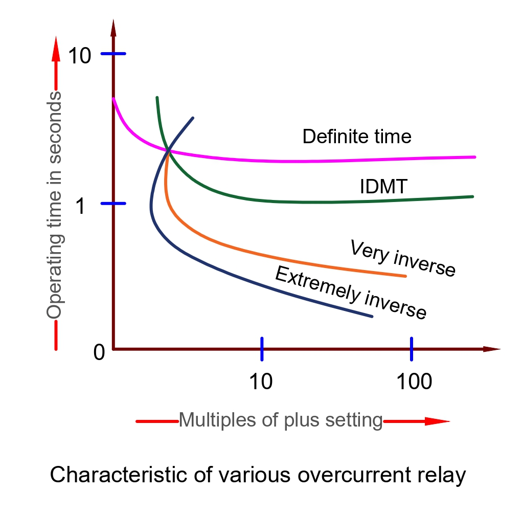
Normal Inverse Relay
These relays have smaller operating times with a change in the current magnitude changes. These relays are used in utility systems.
Very Inverse Relay
The overcurrent relay with the very inverse characteristic curve is used in the feeder and on long transmission lines. The fault current falls at a rapid rate in the transmission line and therefore this relay curve is suitable for the protection of the transmission line.
Extremely Inverse Relay
The extremely inverse relay has an extremely large characteristic time as compared to IDMT and the very inverse relay. The relay trips faster when the pickup value exceeds the relay setting time. The relay is used for the protection of cables and transformers. This relay is used for protecting the cable, transformer, etc.
Long Time Inverse Overcurrent Relay
The relay has an extremely long operating time. These relays are used for those installations where there is a low risk of faults because these relays are not as sensitive as other types of overcurrent relays. It can take up to 60 seconds for clearing the fault.
Inverse Definite Minimum Time (IDMT) Relays
A purely inverse-time relay is an ideal relay where the speed of operation increases commensurate with the amount of the overcurrent. In a practical scenario, however, an inverse-time relay has its own limitations.
As the current input to the system rises, the current transformer output rises causing the induction disc to rotate at a rapid speed and cause the circuit to break. But if the fault current is severely high, the core of the current transformer saturates.
Thus, the current output from the secondary of the Current Transformer stops rising proportionally even though the primary current rises because further magnetization of the CT stops. As a result, the induction disc of the relay can’t operate at a higher speed than that at the point of saturation of the current transformer.
Hence, the speed of the induction disc at the point of saturation is known as its maximum speed of operation. This is the minimum possible time for the relay to operate and it can’t be reduced further hence the name “minimum time”. The relay from this point onwards operates like a definite-time relay irrespective of the amount of rise in the current.
Applications of Overcurrent Relays
The really is used for protection of the following equipment.
- Feeder line protection
- Transformer Protection
- Motor Protection
- Capacitor bank protection
very good website link for all electrical engineer