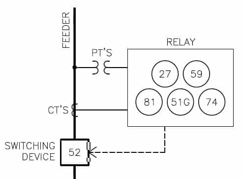
The ANSI standard device numbers ( As per ANSI/IEEE standard C37.2) are used in the design of an electrical power system. These devices protect the electrical network in the case of a fault in the system. The list of ANSI device numbers with their acronyms is as given below.
List of ANSI device numbers and acronyms
- 1 – Master Element
- 2 – Time-delay Starting or Closing Relay
- 3 – Checking or Interlocking Relay, complete Sequence
- 4 – Master Protective
- 5 – Stopping Device, Emergency Stop Switch
- 6 – Starting Circuit Breaker
- 7 – Rate of Change Relay
- 8 – Control Power Disconnecting Device
- 9 – Reversing Device
- 10 – Unit Sequence Switch
- 11 – Multifunction Device
- 12 – Overspeed Device
- 13 – Synchronous-Speed Device
- 14 – Underspeed Device
- 15 – Speed or Frequency Matching Device
- 16 – Data Communications Device
- 17 – Shunting or Discharge Switch
- 18 – Accelerating or Decelerating Device
- 19 – Starting-to-Running Transition Contactor
- 20 – Electrically-Operated Valve ( Solenoid Valve )
- 21 – Distance Relay
- 21G – Ground Distance
- 21P – Phase Distance
- 22 – Equalizer circuit breaker
- 23 – Temperature control device, Heater
- 24 – Volts per hertz relay
- 25 – Synchronizing or synchronism-check device
- 26 – Apparatus thermal device, Temperature Switch
- 27 – Undervoltage relay
- 27P – Phase Undervoltage
- 27S – DC undervoltage relay
- 27TN – Third Harmonic Neutral Undervoltage
- 27TN/59N – 100% Stator Earth Fault
- 27X – Auxiliary Undervoltage
- 27 AUX – Undervoltage Auxiliary Input
- 27/27X – Bus/Line Undervoltage
- 27/50 – Accidental Generator Energization
- 28 – Flame Detector
- 29 – Isolating Contactor
- 30 – Annunciator Relay
- 31 – Separate Excitation Device
- 32 – Directional Power Relay
- 32L – Low Forward Power
- 32H – High Directional Power
- 32N – Wattmetric Zero-Sequence Directional
- 32P – Directional Power
- 32R – Reverse Power
- 33 – Position Switch
- 34 – Master Sequence Device
- 35 – Brush-Operating or Slip-ring Short Circuiting Device
- 36 – Polarity or Polarizing Voltage Device
- 37 – Undercurrent or Underpower Relay
- 37P – Underpower
- 38 – Bearing Protective Device / Bearing Rtd
- 39 – Mechanical Condition Monitor ( Vibration )
- 40 – Field Relay / Loss of Excitation
- 41 – Field Circuit Breaker
- 42 – Running Circuit Breaker
- 43 – Manual Transfer or Selector Device
- 44 – Unit Sequence Starting Relay
- 45 – Fire Detector
- 46 – Reverse-Phase or Phase Balance Current Relay or Stator Current Unbalance
- 47 – Phase-Sequence or Phase Balance Voltage Relay
- 48 – Incomplete Sequence Relay / Blocked Rotor
- 49 – Machine or Transformer Thermal Relay / Thermal Overload
- 49RTD – RTD Biased Thermal Overload
- 50 – Instantaneous Overcurrent Relay
- 50BF – Breaker Failure
- 50DD – Current Disturbance Detector
- 50EF – End Fault Protection
- 50G – Ground Instantaneous Overcurrent
- 50IG – Isolated Ground Instantaneous Overcurrent
- 50LR – Acceleration Time
- 50N – Neutral Instantaneous Overcurrent
- 50NBF – Neutral Instantaneous Breaker Failure
- 50P – Phase Instantaneous Overcurrent
- 50SG – Sensitive Ground Instantaneous Overcurrent
- 50SP – Split Phase Instantaneous Current
- 50Q – Negative Sequence Instantaneous Overcurrent
- 50/27 – Accidental Energization
- 50/51 – Instantaneous / Time-delay Overcurrent relay
- 50/74 – Ct Trouble
- 50/87 – Instantaneous Differential
- 51 – AC Time Overcurrent Relay
- 51G – Ground Time Overcurrent
- 51LR – AC inverse time overcurrent (locked rotor) protection relay
- 51N – Neutral Time Overcurrent
- 51P – Phase Time Overcurrent
- 51R – Locked / Stalled Rotor
- 51V – Voltage Restrained Time Overcurrent
- 51Q – Negative Sequence Time Overcurrent
- 52 – AC circuit breaker
- 52a – AC circuit breaker position (contact open when circuit breaker open)
- 52b – AC circuit breaker position (contact closed when circuit breaker open)
- 53 – Exciter or Dc Generator Relay
- 54 – Turning Gear Engaging Device
- 55 – Power Factor Relay
- 56 – Field Application Relay
- 57 – Short-Circuiting or Grounding Device
- 58 – Rectification Failure Relay
- 59 – Overvoltage Relay
- 59B – Bank Phase Overvoltage
- 59P – Phase Overvoltage
- 59N – Neutral Overvoltage
- 59NU – Neutral Voltage Unbalance
- 59P – Phase Overvoltage
- 59X – Auxiliary Overvoltage
- 59Q – Negative Sequence Overvoltage
- 60 – Voltage or Current Balance Relay
- 60N – Neutral Current Unbalance
- 60P – Phase Current Unbalance
- 61 – Density Switch or Sensor
- 62 – Time-Delay Stopping or Opening Relay
- 63 – Pressure Switch Detector
- 64 – Ground Protective Relay
- 64F – Field Ground Protection
- 64R – Rotor earth fault
- 64REF – Restricted earth fault differential
- 64S – Stator earth fault
- 64S – Sub-harmonic Stator Ground Protection
- 64TN – 100% Stator Ground
- 65 – Governor
- 66 – Notching or Jogging Device/Maximum Starting Rate/Starts Per Hour/Time Between Starts
- 67 – AC Directional Overcurrent Relay
- 67G – Ground Directional Overcurrent
- 67N – Neutral Directional Overcurrent
- 67Ns – Earth fault directional
- 67P – Phase Directional Overcurrent
- 67SG – Sensitive Ground Directional Overcurrent
- 67Q – Negative Sequence Directional Overcurrent
- 68 – Blocking Relay / Power Swing Blocking
- 69 – Permissive Control Device
- 70 – Rheostat
- 71 – Liquid Switch, Level Switch
- 72 – DC Circuit Breaker
- 73 – Load-Resistor Contactor
- 74 – Alarm Relay
- 75 – Position Changing Mechanism
- 76 – DC Overcurrent Relay
- 77 – Telemetering Device, Speed Sensor
- 78 – Phase Angle Measuring or Out-of-Step Protective Relay
- 78V – Loss of Mains
- 79 – AC Reclosing Relay / Auto Reclose
- 80 – Liquid or Gas Flow Relay
- 81 – Frequency Relay
- 81O – Over Frequency
- 81R – Rate-of-Change Frequency
- 81U – Under Frequency
- 82 – DC Reclosing Relay
- 83 – Automatic Selective Control or Transfer Relay
- 84 – Operating Mechanism
- 85 – Pilot Communications, Carrier or Pilot-Wire Relay
- 86 – Lock-Out Relay, Master Trip Relay
- 87 – Differential Protective Relay
- 87B – Bus Differential
- 87G – Generator Differential
- 87GT – Generator/Transformer Differential
- 87L – Segregated Line Current Differential
- 87LG – Ground Line Current Differential
- 87M – Motor Differential
- 87O – Overall Differential
- 87PC – Phase Comparison
- 87RGF – Restricted Ground Fault
- 87S – Stator Differential
- 87S – Percent Differential
- 87T – Transformer Differential
- 87V – Voltage Differential
- 88 – Auxiliary Motor or Motor Generator
- 89 – Line Switch
- 90 – Regulating Device
- 91 – Voltage Directional Relay
- 92 – Voltage And Power Directional Relay
- 93 – Field-Changing Contactor
- 94 – Tripping or Trip-Free Relay
- 95 – For specific applications where other numbers are not suitable
- 96 – Transmitter
- 97 – For specific applications where other numbers are not suitable
- 98 – For specific applications where other numbers are not suitable
- 99 – For specific applications where other numbers are not suitable
| Read Next : ANSI Codes of Frequency Protection Relay |