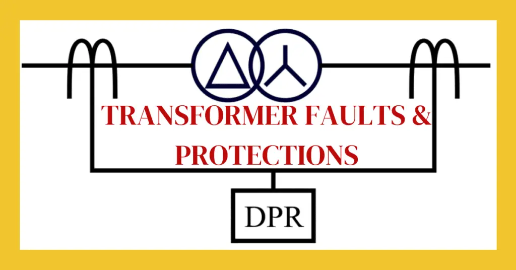
In this article, we will discuss transformer faults and transformer protection schemes. In the electrical power system, the transformer is an important electrical machine that is used for stepping up and down the voltage and current in transmission lines.
If there is any fault occurs in the system, the transformer must be isolated from the system as quickly as possible, otherwise, it could get damaged. Here, we will discuss different types of transformer faults and protection schemes used for transformers.
Types of Transformer Faults
Depending on the part of the transformer in which the fault occurs, the transformer faults are classified into the following three types:
- Faults in transformer winding and connections,
- Faults in the auxiliary equipment of the transformer,
- Faults due to overload and external short circuits.
Now, let us discuss each category of transformer in more detail.
1. Faults in Transformer Winding and Connections
Winding and connection faults in a transformer occur due to the unbalanced current flowing through the transformer windings. These types of faults are severe because they can immediately damage the transformer windings. These faults include phase-to-phase faults, phase-to-earth faults, etc.
The inter-turn short circuit occurs in transformer windings mainly due to insulation failure or mechanical forces. Under short circuit condition of windings, a heavy current flow through the windings which in turn causes the emission of a huge amount of gas due to transformer oil decomposition. However, these faults are easily datable but they require instant clearance to avoid heavy damage to the transformer.
2. Faults in the Auxiliary Equipment of Transformer
These faults occur in auxiliary equipment of the transformer such as insulation, conservator tank, transformer oil, etc. These faults can cause damage to the winding of the transformer. Hence, these faults have to be detected and cleared as quickly as possible.
- Faults due to Insulation Failure – The failure of insulation of the core and windings causes major faults to develop in the transformer. This fault is mainly due to the use of poor insulation material, overcurrent flow, etc.
- Faults due to Gas Cushion – The transformer insulation and oil are greatly influenced by the presence of oxygen and moisture. To avoid faults due to oxygen and moister, the conservator tank and breather must function effectively.
- Faults due to Transformer Oil Breakdown – Transformer oil acts as an insulator as well as a coolant. Therefore, the temperature and insulation level of the oil must be maintained at a certain level to avoid faults in the transformer.
3. Faults due to overload and external short circuit
The overload and external short circuits cause heavy currents to flow through the transformer windings. This results in insulation failure. Therefore, to avoid transformer faults, we must prevent overload and external short circuits in the system as much as possible.
Let us now discuss different protection schemes used in transformers.
Transformer Protection Schemes
Different transformer protection schemes are employed based on the size of the transformer and its rating. Some common protection schemes for transformers are described below.
1. Buchholz Relay
Buchholz relay is a gas-actuated relay. Under normal operating conditions, the Buchholz relay is completely filled with oil. When a fault occurs and gas bubbles are formed in the transformer tank. The gas starts accumulating in the relay chamber.
Buchholz relays help in detecting minor as well as major faults in the transformer. For minor faults, it gives an alarm, and for major fault events, it trips the circuit.
2. Differential Protection
The differential protection scheme is used to protect the transformer against phase-to-phase faults and phase-to-ground faults. It is also known as circulating current protection. The operation of differential protection is based on the comparison of currents flowing in the primary and secondary windings of the transformer.
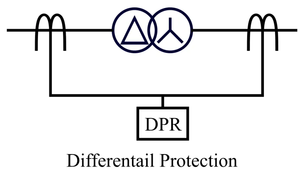
When the incoming current is equal to the output current, it means there is no fault inside the transformer. Here, I considered a transformer with a unity turn ratio. On occurring of faults inside the transformer, the outgoing current of the transformer can not be equal to the incoming current because now, the current has got another path. Thus, when the differential protection relay observes the difference in the current exceeds the set limit, it trips the circuit breaker.
The differential protection scheme protects the transformer from winding short circuit faults and inter-turn faults.
3. Harmonic Restraint Relay
To protect the transformer against the magnetizing inrush currents, the harmonic restraint relay is used. This protection scheme consists of a series LC circuit that allows only the fundamental harmonic component of the inrush current to flow through the operating coil and the DC component and all the higher harmonic components are made to flow through the restraining coils. The harmonic restraint relay blocks the second and fifth-order harmonics during the charging of the transformer.
4. Overcurrent Protection
For small transformers of rating below 10 MVA, HRC fuses are used to protect the transformer against overcurrent. Above 10 MVA transformers, the overcurrent relays are used. An overcurrent relay operates when the current in any phase exceeds the peak value of the setting. The major types of overcurrent protection used are instantaneous overcurrent protection, time overcurrent phase protection, ground fault instantaneous overcurrent protection, and time-ground fault overcurrent protection.
5. Restricted Earth Fault Protection
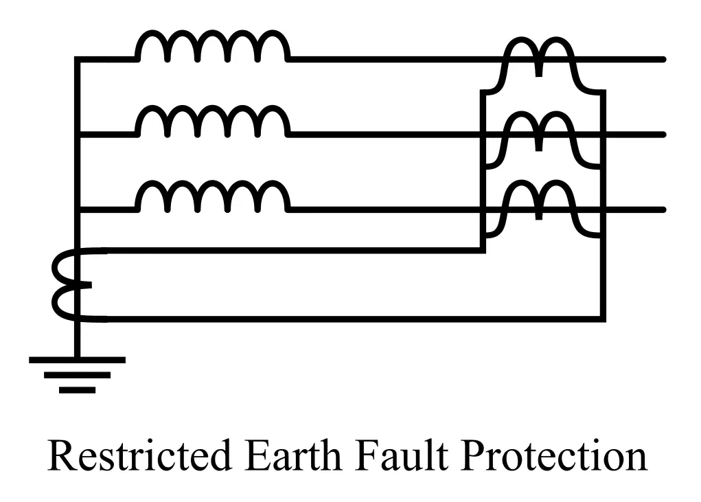
Restricted earth fault protection protects the transformer windings from earth fault. It is used to protect the transformer in the zone between the start connected winding and the earthed neutral terminal of the transformer. The restricted earth fault protection is implemented by using a set of phase current transformers and neutral current transformers.
In each phase, one current transformer is connected and all secondary winding of CTs is connected in parallel. The final output of all CTs are vector sum of zero sequence currents and it represents the unbalance current or earth fault current. The earth fault relay is connected across the three secondary winding of CTs.
When there is no fault inside the transformer, the vector sum of the line current is equal to the neutral current and the relay does not pick in this case. In the event of a fault, the vector sum of the line current can not be equal to the current flowing in the neutral CT, and in this case, the difference in the current causes the tripping of the relay.
6. Over-Fluxing Protection
Over-fluxing increases the temperature of the transformer and causes damage to it. To protect the transformer against over-fluxing, a V/Hz over excitation relay is used which operates at a too-high voltage or at a too-low frequency. when the transformer operates at its rated voltage and frequency, the flux in the core remains equal to its designed flux density.
However, with any change in the voltage or frequency from its design value, over-fluxing happens. The over-fluxing relay continuously monitors the V/f ratio and issues a trip command to the circuit breaker when the over-fluxing reaches 110% of the rated value.
7. Sudden Pressure Relay
The sudden pressure relay is used to protect the transformer against internal arcing which suddenly increases the pressure in the transformer tank. The sudden increase in the tank pressure is caused by the internal faults inside the transformer. If the tank pressure increases above its design capacity, there are chances of tank explosion. The relay senses the sudden increase in pressure and issues a trip command to the circuit breaker to isolate the transformer from the supply source.
8. Thermal Overload and Temperature Relays
Thermal overload and temperature relays measure the temperature of the transformer oil. For a specified oil temperature, this relay controls the operation of cooling pumps and fans. Under the condition of overheating, a warning alarm is given. At very high temperatures, this relay trips the circuit breaker.
The relay monitors the oil temperature and switches on or off the pump to control the temperature. It generates an alarm signal when the temperature reaches the alarm setting of the oil temperature. The relay trips the circuit breaker when the oil temperature exceeds 95°C.
Hence, this is all about transformer faults and transformer protection schemes.