A voltage divider circuit is formed using two resistors connected in the series, and the circuit outputs a portion of its input across resistors.
Voltage division is a process in which a single high voltage is divided into multiple values to obtain smaller values of voltage for different applications. The circuit employed for this purpose is called a voltage divider.
What is a Voltage Divider?
An electrical circuit that consists of various resistors connected in series and provides multiple voltages across different resistors from the single supply source is referred to as a voltage divider.
Therefore, a voltage division circuit is simply a series resistive network that splits a single voltage into smaller voltages. This circuit is sometimes also called a potential divider.
Component of Voltage Divider
A voltage division circuit typically has two primary elements namely: two or more resistors and a battery or source of voltage.
The battery provides a higher supply voltage, and the resistors are connected in series to split the battery voltage into multiple smaller values.
Circuit Diagram of Voltage Divider
A typical voltage division circuit diagram is shown in the following figure.
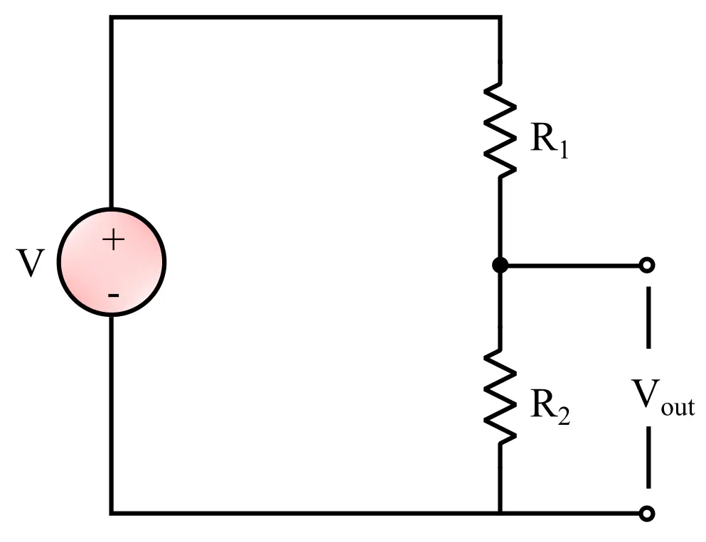
From the circuit diagram, it consists of a source of voltage, i.e. battery, and two resistors connected in series, and are connected across the battery.
Principle of Voltage Divider
The working principle of a voltage divider is based on the voltage division rule.
According to this rule, the total applied voltage to a series network of resistors is distributed among resistors based on their resistance values.
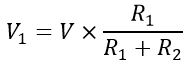
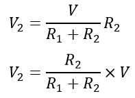
For example, if V is the total supply voltage, R1 and R2 are two resistances connected in series, then, according to the voltage division rule,
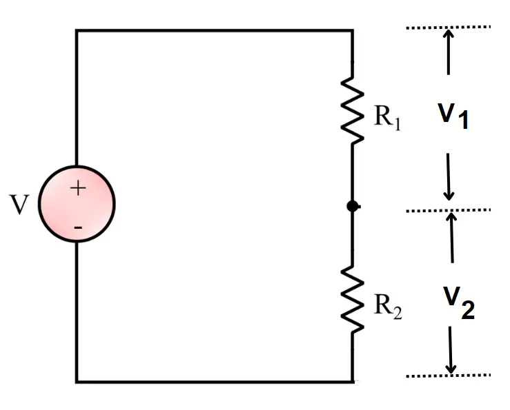
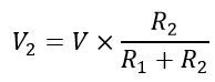
And,
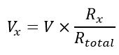
In general,
Operation of a Voltage Divider
We can analyze the operation of a voltage division circuit under two conditions, i.e. unloaded condition and loaded condition.
Case I – Equation of voltage Divider in Unloaded condition
The circuit diagram of the unloaded voltage division circuit is shown in the following figure.

In this case, the load circuit remains open, and no current flows outside the voltage division loop.
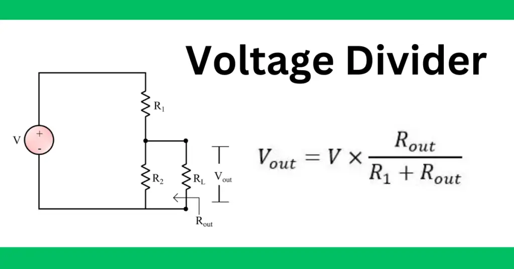
In this case, the output voltage is given by,
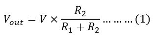
This is a voltage divider formula.
Proof of Voltage Divider Equation
We can prove equation (1) using Ohm’s Law(V=IR).
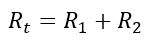
The resistance R1 and R2 are connected in the series, therefore the total resistance of the circuit is equal to the sum of resistances.
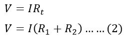
The same current flows in both resistance because resistances are connected in the series. Let the circuit current be I. The total voltage across both resistances is equal to the input voltage.
Therefore,
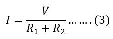
The current flowing in the circuit is;
The voltage across resistor R2 is;
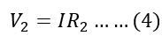
Putting the value of the current from equation(3) in equation (4), we get,
Case 2 – Loaded Voltage Divider
The circuit diagram is shown in the following figure.
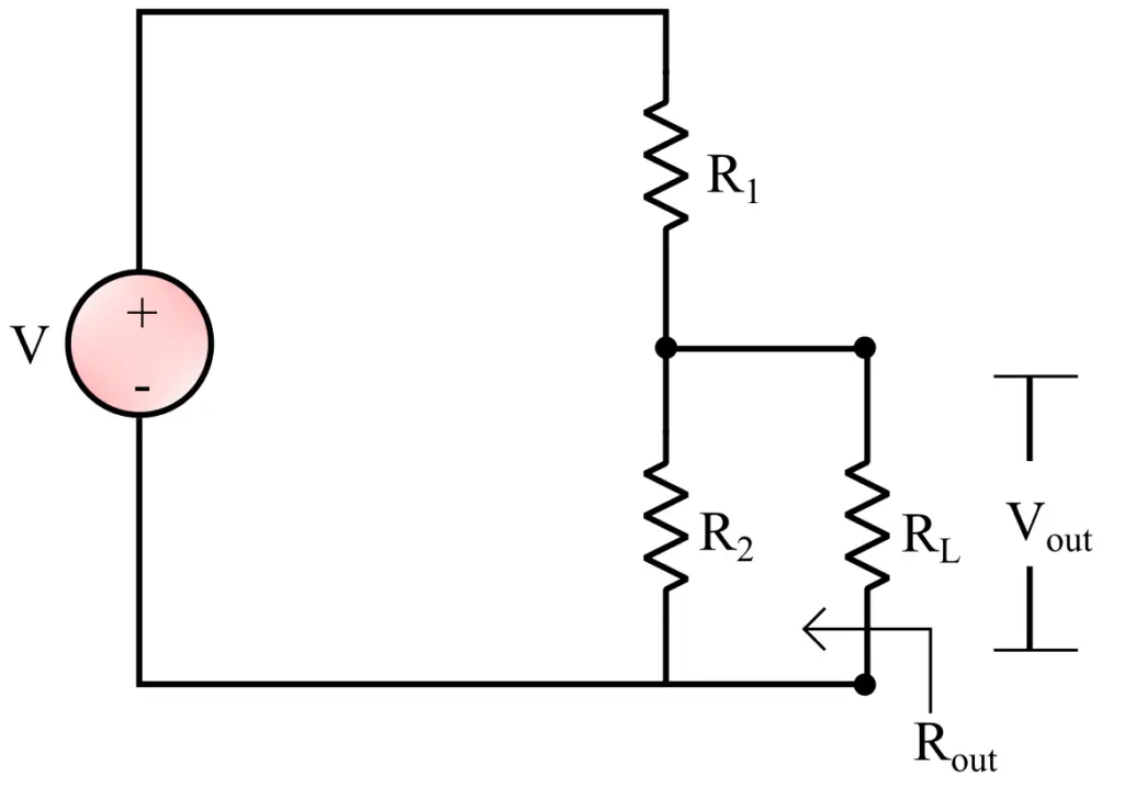
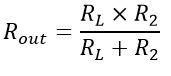
In this circuit, it can be seen that the load resistance RL and R2 are connected in parallel. Thus, the equivalent resistance is given by,
Therefore, the output voltage of the circuit is given by,
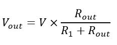
The equation is proved.
Types of Voltage Dividers
There are three types of voltage dividers.
Resistive Voltage Dividers
These are built with two resistors. The resistors are connected in the series. The circuit diagram is shown below. They are suitable for AC and DC.

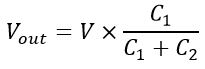
Capacitive Voltage Dividers
The capacitive dividers are built by connecting two capacitors in the series with AC supply. Unlike resistive division circuits, they can function for AC supply.
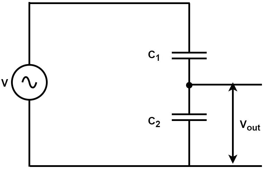
The voltage across capacitor C2 is;
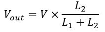
Inductive Voltage Dividers
Inductive voltage dividers have two coils connected in the series with an AC supply.
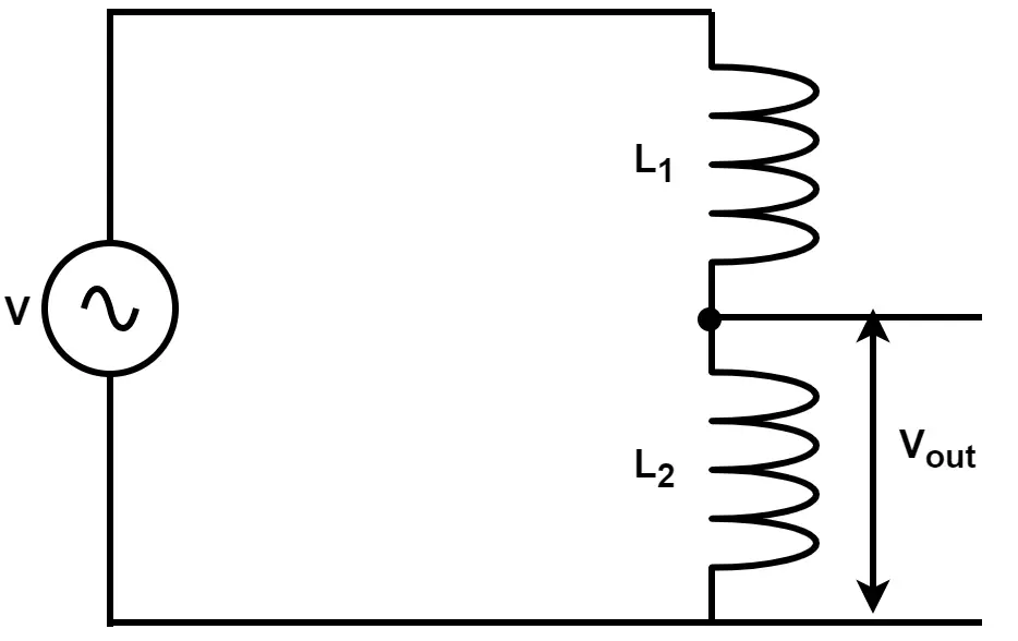
An example of an inductive voltage divider is the autotransformer that is used to get the variable voltage by changing the inductance of the circuit. The output voltage across the inductor is;
Applications of Voltage Divider
The following are some key applications.
- Used to obtain multiple voltages from a single source of voltage.
- It is also used in multimeter-like electronic measuring devices.
- Voltage dividers are commonly used in different bridges like the Wheatstone Bridge.
- They are also employed in high-voltage measurement applications.
- Used in potentiometers
- Used in the sensors like thermistors, photo sensors, and force-sensitive resistors.
- They are also used for signal attenuation at low frequencies.
Conclusion
In conclusion, a voltage divider is simply a series resistive network that can split large single voltage into small multiple voltages and finds applications in various electrical and electronic systems like multimeters, bridges, digital circuits, and more.
Numerical Example
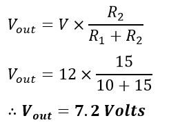
An unloaded voltage divider circuit has two resistors connected in series, R1 = 10 Ω and R2 = 15 Ω. This combination is connected across a battery of 12 volts. What will be the output voltage across the resistor R2?
Solution:
The circuit diagram of the given problem is shown below.
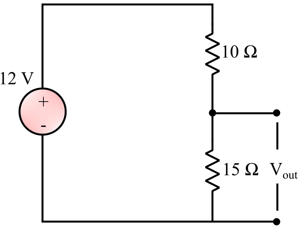
According to the voltage division rule, we get,