This article describes the wiring diagram of PLC and DCS for Digital Input (DI), Digital Output (DO), Analog Input (AI), and Analog Output (AO) signals.
Types of Input and Output in PLC & DCS
There are four types of inputs and outputs in PLC and DCS systems.
- Digital Input
- Digital Output
- Analog Input
- Analog output
1. Digital Input
Instruments such as pressure switch, level switch, temperature switch, flow switch, vibration switch, on-off feedback of valve, a run indication of any drive, etc are connected to the digital input card of the PLC and DCS.
2. Digital Output
The digital output card of the PLC and DCS is used for giving commands to the on-off valve for opening and closing, to give a start command to any drive, or stop any drive.
3. Analog Input
Mainly transmitters like pressure transmitters, level transmitters, temperature transmitters, flow transmitters, vibration transmitters, control valve opening feedback, running drive’s current, etc are connected to the analog input card of the PLC and DCS.
4. Analog Output
Opening command to control valve and load change of a drive running on VFD are connected to the analog output card of the PLC and DCS.
Let us see the connections of the field instruments with the cards which we mentioned above.
(Note that in below mentioned loops, only the basic idea of the loops is given. In the field or in plants, the actual loops have components like fuses, barriers, isolators, and repeaters. Also, multi-core cables are used. The multi-core cables coming from the field are terminated into Field Termination Assembly (FTA) and a special type of cable connects the FTA with the IO cards)
Wiring Diagrams of PLC and DCS with Field Instruments
The different wiring schemes of field instruments with PLC and DCS are as follows.
1. Digital input signal wiring with PLC and DCS
1.1 Two-wire connection
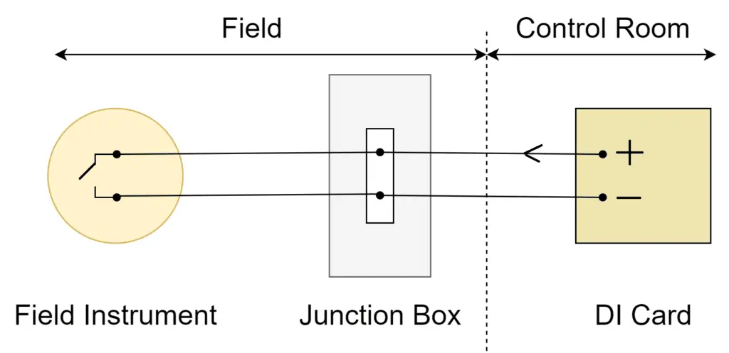
The above figure shows a two-wire connection for a digital input to the PLC. The digital input card of the PLC is sued to monitor a digital contact in the field. Whenever the contact in the field changes, a change in the voltage is sensed by the digital input card. Suppose the field contact of any switch is open, then the digital input card’s channel will not receive any voltage back. When the same contact closes, the voltage is returned to the digital input card’s channel.
1.2 Two-wire connection with loop monitoring
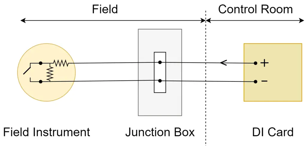
The two-wire connection with loop monitoring is the special version of the above-mentioned two-wire connection.
Why is this type of configuration required?
Suppose in the first case, if the normally open contact is used and in case of the parameter is high, the contact will become closed. On sensing closed contact, the plant should trip. In this case, if the cable is in broken condition, then what will happen? The digital input card will always receive open contact and never trip the plant. So, the resistors used in the circuit will come into the picture for a two-wire connection with a loop monitoring configuration.
The digital input card will always have a raw value instead of open contact. Hence, whenever the cable breaks, the raw value of the digital input card will become zero, and the digital input card will consider a kind of fault. Thus, these resistors will help in the identification of the cable break.
1.3 Wet contact type connection
2. Digital output signal wiring with PLC and DCS
2.1 Two-wire connection
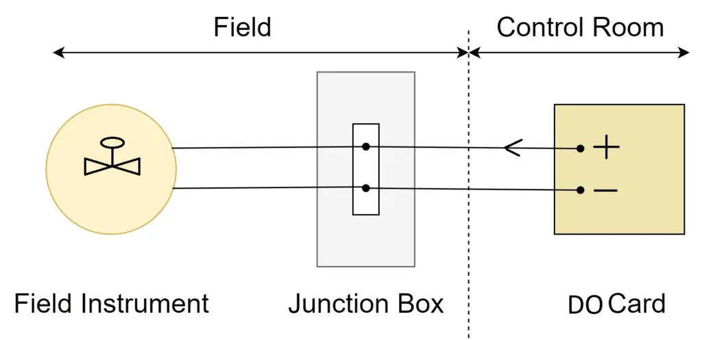
The simple form of a Digital Output connection is shown above. The digital output card will supply the output voltage. This output voltage will directly actuate the field instrument. Generally, the output voltage is limited to 24 volts.
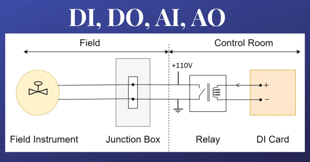
2.2 Wet contact type connection
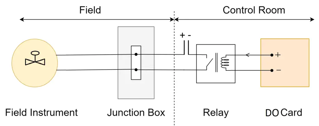
This is another form of digital output connection. This type of digital output connection requires a relay between the field instrument and the digital output card. The digital output card will actuate the relay’s coil as shown in the figure. The Voltage as shown by + – (it can be 110 VDC, 24 VDC, or any other voltage) will be supplied to the field instrument. When the relay gets de-energized, at that time no voltage will go to the field instrument. This way we can operate a high-voltage operating instrument using a PLC or a DCS DO card.
3. Analog Input signal wiring with PLC and DCS
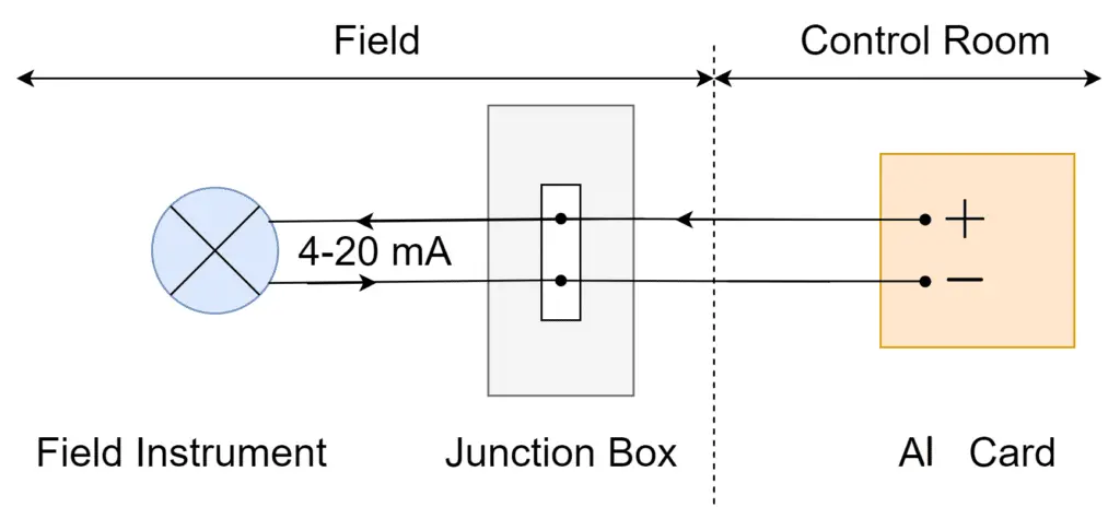
Generally, a 4 mA to 20 mA loop is used in the analog input signal type connection. In a 4 mA to 20 mA loop, 24 VDC I is the supply voltage from the analog input card. Due to the change in the physical quantity sensed by the field instrument, the loop current also varies (the transmitter’s electronics do this work of converting physical quantity into electrical current). Now, this loop current is sensed by the Analog Input card connected to the PLC or the DCS.
4. Analog output signal wiring with PLC and DCS
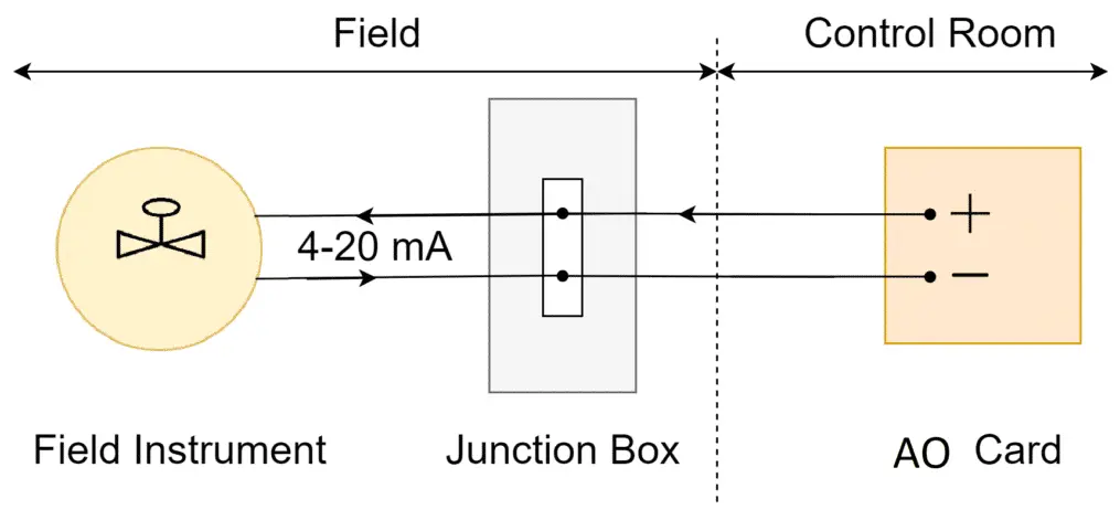
The analog output card does the inverse of the analog input card. The card generates 4 mA to 20 mA according to the PLC or the DCS command. This current is directly given to the field instrument which is generally a control valve.