DCS and MCC Interface Philosophy is very important and the implementation of the system varies from plant to plant. Every drive in the plant is controlled by the Distributed Control System (DCS) through a control signal. The control signal is given to the Motor Control Center (MCC) for turning ON or stopping the motor or say electric drive.
For the mutual communication of the DCS and MCC, there is a control philosophy to make the system easier. Many times, due to a lack of knowledge we do mistakes or miss any important points.
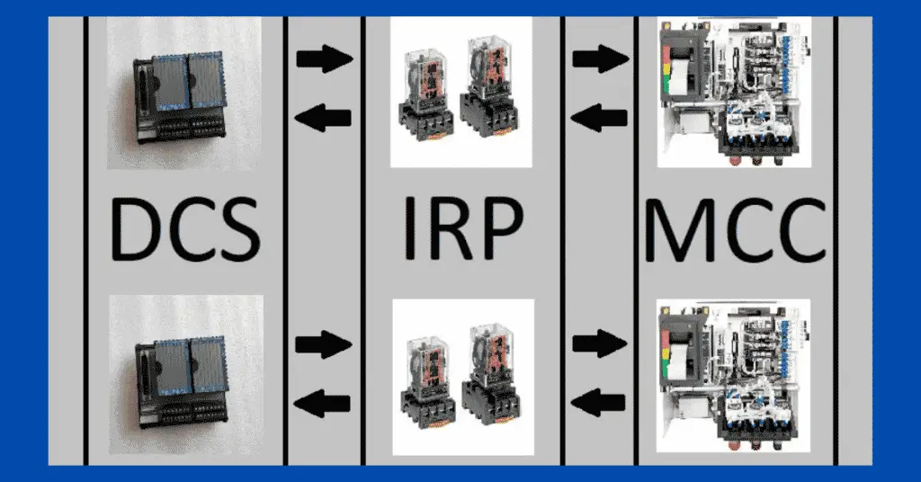
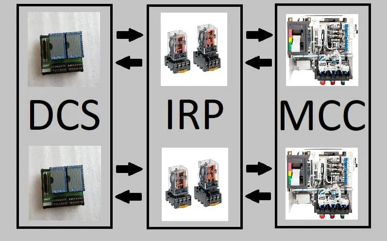
Let us see the most important philosophy of any plant i.e. Distributed Control System & Motor Control Center Interface Philosophy. DCS and MCC interface and communicate with each other through the use of relays. On one side contact change over is used and on the other side operates the relay as per the conditions or logic.
- DCS gives a start command from the Digital Output Card to the MCC for starting any drive. This start command is momentary for a few seconds like 1 second to 2 seconds.
- Stop command is given to MCC from the DCS to stop any drive. The digital output/stop command is always energized when the drive is running or in stop condition. Whenever a stop command is given from the system, then the digital output drops i.e. becomes 0. This is because the fail-safe condition is used for stopping the drive. So, any cable damage or lost connection will stop the drive.
- MCC gives input to the DCS for run indication. Whenever the drive is running, a continuous signal is present on the digital input of the DCS card.
- Current or power usage is displayed on DCS. MCC has a current transformer and DCS also has a current transformer. Combining these two transformers, the appropriate value of current after scaling is given to the analog input card of the DCS.
- MCC gives speed indication to the DCS
- In the case of Variable Frequency Drive (VFD), the DCS gives an analog output to the VFD for controlling the drive’s speed.
- DCS receives the digital input signal from the MCC for local and remote indications of the drive.
- DCS receives one more signal from the MCC in terms of digital input which shows the healthiness of the drive from the MCC. If there is any trip from MCC or any fault in MCC, then this signal shows electrically drive not ready.
For making all this signal communicate between DCS and MCC, relays are used. The main purpose of using the relays is to physically isolate both the systems i.e. DCS and MCC. The reason to isolate both the systems is that the DCS works on a few volts like a maximum of 24 volts. While on the other hand, the MCC uses volts in multiples of hundred volts.
Hence even one spike of MCC volts on DCS will destroy the total DCS costing crores of rupees. For this purpose, some industries have Interposing Relay Panel which is known as IRP. The IRP is having all replays which makes communication possible between the DCS and the MCC.
For the relay used in the IRP(Interposing Relay Panel) , there are two control philosophies, one way is controlling the relay and another way is using the contact of the relay. Now the confusion arises that which side will give voltage to detect the change in contact. Because to detect the contact changeover, a voltage is needed.
Now the solution for this is very simple. Suppose DCS wants to know the status of the drive, whether the drive is running or not. In this case, DCS will give 24 volts to one side of the contact and whenever this contact changes its state, DCS will receive the 24 volts back if the contract closes. It does not receive a 24-volt loop if the loop breaks.
If the drive is controlled by any ESD system, then the ESD system separately issues the command to the MCC for controlling the drive. All signals are hard-wired as they are used in the DCS system.
During the commissioning phase, these all signals are tested to ensure the proper working of the control system to control drives. The drives are placed in test mode during the testing of the drives. In test mode, the drive will not start or stop actually, but the feedback will come for the given signal to start or stop. This process of keeping the drive in the test mode is done by an electrical team in the sub-station.
Thus, DCS and MCC interface is very important for driving the drives from the remote location.