In this article, we will discuss the flow transmitter calibration procedure. Differential pressure type flow transmitters are widely used to measure the flow in the plant. Before moving ahead in this article you may have a look at the Basics of Flow Measurement.
Various flow measuring devices like Differential Pressure type flow meter, Magnetic type flow meter, Ultrasonic type flow meter, Vortex type flow meter and Coriolis flow meter are used in plants to measure the flow.
Differential pressure can be generated through the Orifice, Venturi, Pitot tube, and averaging pitot tube.
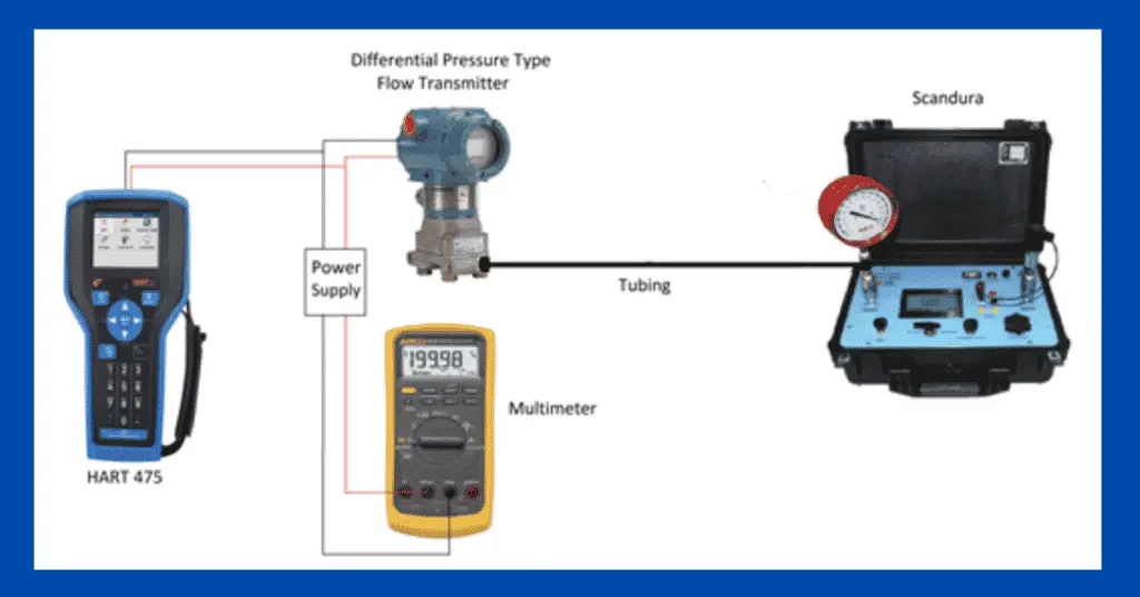
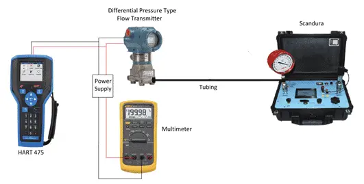
For doing the calibration of a differential pressure type flow transmitter, the following equipment is required.
- Differential Pressure type flow meter to be calibrated
- Scandura or any other pressure-generating device in the mmH2O range
- A calibrated pressure gauge of an appropriate range
- Power supply – If the pressure transmitter is not connected to the system and needs an external power supply
- Multimeter
- HART
Let us now discuss the calibration procedure of the Differential Pressure type flow meter.
Below is the procedure to do the calibration of a Differential Pressure type flow meter
Calibration Procedure
The following steps are required to be followed for flow transmitter calibration.
Step-1
The Differential Pressure type flow meter to be calibrated should be powered on through the loop cables through which connected to the system or through an external power supply.
Step-2
If the Differential Pressure type flow meter is in the field, then isolate the Differential Pressure type flow meter. Flush the Differential Pressure type flow meter in a closed drain if used to measure the flow of hazardous chemicals.
Step-3
Connect the multimeter in a series configuration with a Differential Pressure type flow meter. Do not forget to connect the leads to mA and the common terminal on the multimeter. Many times, we fail to change the lead configuration in the multimeter.
Step-4
Now connect the Differential Pressure type flow meter to the Scandura by using proper tubing. Here, we used a Scandura because the range of Differential Pressure type flow meter is generally in mmH2O only.
Step-5
Connect a pressure gauge to the tubing connecting the Scandura and the transmitter. The extra pressure gauge is used to avoid errors sometimes caused in the display of the Scandura.
Step-6
We need two ranges of the Differential Pressure type flow meter which is used in the field. One is the input range in mmH2O and the other is the range in m3/hr. A datasheet contains both the range of the Differential Pressure type flow meter. Now using Scandura we need to give inputs in steps of 25% starting from 0% of the range of mmH2O. Check for leakages in the tubes. If present, arrest it.
Step-7
As we know that flow is proportional to the square root of the differential pressure. So the output in m3/hr will not be in direct proportion to the mmH2O. For converting it, use the following table.
| mmH2O % | m3/hr % |
| 0 | 0 |
| 25 | 50 |
| 50 | 70.7 |
| 75 | 86.6 |
| 100 | 100 |
Step-8
Similarly check the output for 75% value, 50% value 25% value and 0% value. Plot a graph of upward readings and downward readings we got from the readings we obtained from the steps we followed. This helps to know the hysteresis of the transmitter we are using.
Step-9
Now calculate the error percentage from the values we got by the above steps. If the error percentage obtained is within the acceptable limits per process requirement, then the transmitter is ok. If the error obtained is more than the maximum error permissible as per process then zero and span calibration of the transmitter is needed.
Step-10
If an error is greater than the maximum permissible error, then apply the 0% value and check whether it is ok or not. If it is not ok, then connect the HART and apply zero trim. Now the transmitter should show the exact 0% value.
Step-11
Now check the 100% value by applying the pressure. If it is ok, then move to Step 6. If it is not ok, then apply span trim from the HART. After applying the span trim, the transmitter should show the exact 100% value. Now move to step 6 and again repeat all steps.
Step-12
Now take the Differential Pressure type flow meter in line.