The loop check refers to the entire control loop checking starting from the primary sensor element to the final actuation component and a feedback loop. Loops are one of the most important parts of the control system. The controllers of the DCS or PLC communicate with the field devices with the loops.
Types of Loops in Control System
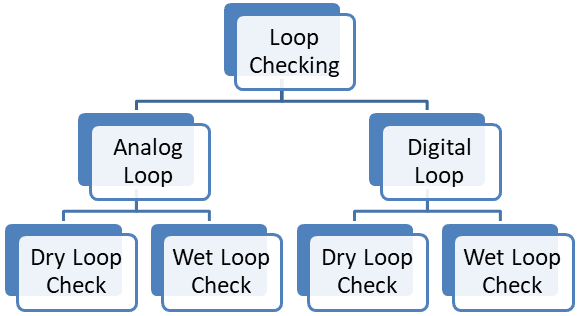
There are two types of loops in any system. One is the analog loop that carries 4 mA to 20 mA current for transmitters, such as pressure transmitters, flow transmitters, temperature transmitters, level transmitters, and vibration transmitters. Analyzers like pH analyzers, conductivity analyzers, silica analyzers, and TOC analyzers. Fire and Gas devices like CO gas detectors, Cl2 gas detectors, and H2S gas detectors. Another type of loop is the digital loop that carries digital signals like Foundation Fieldbus signal, Profibus PA signal, and Wireless HART signals.
Purpose of Loop Checking
We can verify the following using Loop check.
- All the hardware components of the loop are connected to the system and are functional.
- The input and output cards of the system are OK.
- The wiring to the sensor, transmitter, and PLC is OK.
- The loop is powered by proper supply.
- Ensures face-plates, alarms, graphics, correct configuration, and 4 -20 mA scaling.
Types of Loop Check:
Loop checking is the process of checking loops during the commissioning of the plant. It helps in troubleshooting when we face problems with the transmitter. There are two types of loop checking. One is dry loop checking and the other is wet loop checking. Let us discuss in detail the types of loop checking and the procedure for loop checks.
Dry Loop Check
The purpose of the dry loop check is to identify the cable used for a particular signal.
Wet Loop Check
The purpose of the wet loop check is to identify whether the signal transmitter from the transmitter, analyzer, or gas detector is reaching the control system without any disturbance or not.
Before carrying out a loop check, the following must be completed.
- Complete mechanical construction
- Laying and termination of cables
- Proper installation of PCS, SIS, and other system components.
- SAT is completed.
- Ensure the availability of documentation for all loop components, such as loop drawing, instrument calibration data, PCS configuration, and SMART data
Analog Loop Check:
As discussed previously, analog loops are used for transmitters, analyzers, and F&G gas detectors. For analog loops, two types of loop checking are required. One is dry loop checking and the other is wet loop checking. Dry loop checking is also called cold loop checking. Wet loop checking is also called hot loop checking. Let us discuss the detailed procedure for dry loop checking and wet loop checking.
Every transmitter is assigned a specific channel in the control system. The value of that particular transmitter should reflect on that particular channel only. To verify this, dry loop checking is required to be performed. If the values of one transmitter go into another transmitter, then this will give an erroneous reading and cause vulnerability to the process. In the dry loop checking procedure, the field cables or the control system cables are tested using the continuity testing method. In this method, the cable pair from one end is made Short circuit, and on another end, the cable’s core continuity is measured. This way, we can identify the proper cable pair allocated to the transmitters and terminate them on the proper channels.
Analog signals generally distort with other interferences, hence there is a loss of signal. Due to this signal distortion, the value transmitted from the field transmitters does not reach the control system properly. Hence, there is a problem in controlling the plant parameters or any other adverse effect on the process. For this reason, a loop check is done in the commissioning phase to verify the integrity of the 4 mA to 20 mA current loop.
The analog wet loop check is done in 5 points wet loop check to verify linearity. For 4 mA to 20 mA signals, we check 4 mA, 8 mA, 12 mA, 16 mA, and 20 mA signals, and may be checked in the reverse order as well. In fact, it is good to test at < 3.6 mA and >21 mA to verify the correct NAMUR NE43 failure alarm indication in the control system.
For feeding this signal to the system, we actually apply the parameter to the transmitter. Like we apply pressure to the pressure transmitter, the respective temperature value of RTD to the temperature transmitter, and so on for other transmitters. This way, we can also verify the response of the transmitter. The Analog loop wet loop checking method also helps verify the range configured in the control system and field device.
Many 4-20 mA/HART devices have more than one analog signal, such as Coriolis mass flow transmitter may have three current loops, and therefore we need to check all three current loops.
A 4-20 mA control valve positioner has two current loops, one for the valve setpoint and another for actual position feedback. Therefore, its both current loops should be checked.
Digital Loop Check:
In digital loop checking, two types of loop checking are performed. One is dry loop checking and the other is wet loop checking. Dry loop checking as discussed above is used to verify the cable pair for appropriate control system channel assignment and particular transmitter. In this digital communication, device address also plays a very important role. Therefore, we need to configure the transmitter carefully because wrong mapping leads to a signal swap in the control system graphics. Because in some protocols like Foundation Fieldbus, the main trunk cable carries the signal of more than one transmitter, Hence, device addressing plays a very important role here.
Digital signals are more prone to noise. Hence, proper verification of the cables is required. For this purpose, the wet loop checking of the digital loops is a very crucial process. In addition to the loop checking, Fieldbus Monitor (FBT-6) devices are used to confirm the healthiness of the cables.
The Fieldbus Monitor FBT-6 is the device used to examine the live Foundation Fieldbus network without interfering with the operation of the loop. The Fieldbus Monitor is used for commissioning and maintenance personnel to verify the network operation or to troubleshoot an errant network.
On one end, a transmitter device is used and on another end, a receiver device is used. The transmitter device sends signals of different amplitudes and on the receiver end same signal is received by the receiver. The receiver calculates the noise induces in the signal. This helps to know whether the cable can be used for digital data transfer or not. The term signal strength comes into the picture when we talk of digital communication.