In this article, we will discuss how to do the PLC system site Acceptance Test (SAT). Site Acceptance Test of a PLC system is done at the site after receiving the PLC system from the factory.
SAT of PLC system includes visual checking of all components as per BOM (Bill of Material). Then starting the system and checking all functionalities is the next step. Many more things are also needed to be taken care of. Let us discuss this PLC system SAT procedure in detail.
Before starting the SAT, some important documents are required for doing the SAT of the PLC system. These documents include the BOM of the PLC, architecture of the PLC system, panel wiring diagram, panel interconnection diagrams, power distribution diagram, load distribution details, and input-Output wiring.
Bill of Material (BOM) is a new term here. BOM is one of the most important documents. BOM contains the detail of all the components or cards used for that particular system. Here we are talking of the PLC system, BOM of the PLC system will include details of power supplies, diode O-rings, MCB, Analog Input cards, Analog Output cards, Digital Input cards, Digital Output cards, fuses, barriers, and other special cards if exists for the package. The BOM contains details like the make and model number or part number of the component, the number of components used, and ratings for components like power supply, MCB, and fuse.
As discussed, SAT is done at the installation location itself. SAT is a bit similar to Factory Acceptance Test (FAT). In SAT the PLC system is tested under real process conditions and the performance is noted. The whole PLC system SAT is done in presence of the manufacturer.
SAT of PLC
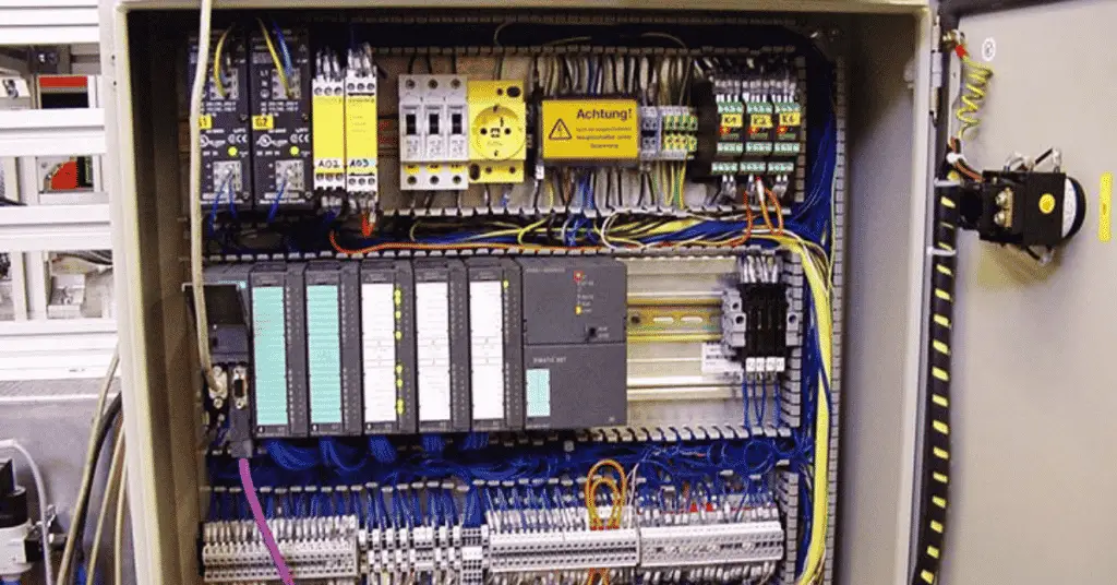
The first step is to physically check the presence of all the components as per the BOM. The main reason for doing this visual check is to ensure that everything is ok. The reason for checking is that the PLC system has been transported from the manufacturer’s place to the site. During transportation, the damage might have occurred. So, we need to visually check the condition of all components of the system.
Check the installation condition, fabrication, and condition of the panels.
Before powering up the system, MCB needs to be thoroughly checked as per ratings as per the design. Check all the wirings of the power supply also.
One more thing to verify before powering ON the panels is the earthing check. Make sure proper earthing is given to the system. Also, verify the condition of the Earth pit (we need to see that the cables from the panel are connected to the earth strip in the pit)
Now check the incoming voltage on the terminal board with the multimeter.
Then check the voltage between earth and neutral It should be below 0.5 volts or as per manufacturer guideline. If everything is found ok, then turn on the MCBs one by one in the panel.
Now check the output voltage at MCB and input voltage at the power supply. Both should be the same. Similarly, check voltage at all contact points for confirmation of proper wirings.
Also, check the condition of all cards. Generally, a green LED is given on cards for showing their health status. All cards should be healthy.
Now check the redundancy of all components which are redundant. For example, PLC has two redundant power supply cards. So, turn off one power supply and check whether all components are working properly or not. Similarly, check for MCBs and redundant Input-Output cards. Whenever any component is turned off, a proper alarm should get generated. Here proper alarm means the alarm should contain the detail for proper identification of the component which has failed including the panel number.
Check the PLC system redundancy by pulling out the redundancy cable. A proper alarm should get registered for the same.
After confirming that the redundancy is working ok, we need to check all input outputs. For verifying this, actuate a digital input and check whether the same is getting reflected on the card or not. Similarly, turn ON a digital output and check whether the output on the terminal block is getting ON or not.
We need to check analog inputs and analog outputs also. We usually check 4 mA to 20 mA for analog circuits. Generate any output using the program and on the terminal block of analog output verify the mA for the same. Similarly, check the analog inputs. Using an mA generator feed mA to the terminal block and check the same on the address of that card.
Check proper alarm getting generated with proper tags. Also, check the trend of analog values.
Also, check the punch point list which was found during FAT. All points should be cleared.
This was all about the system checking in the PLC SAT procedure. If any deviations are found in the procedure shown above, the manufacturer will have to attend the problem. After getting all clear, the plant is ready to start.
The tests we performed covered installation qualification and operational qualification. After the startup of the plant, the production department along with QA/QC department verifies the quality of the product. This is done for ensuring the performance qualification.
After passing the above tests, the relevant authorities or quality department will decide whether to allow the PLC system to operate.
This is all about the PLC system site Acceptance Test (SAT)
best website for all engineers