A control valve positioner is a device that senses the signal from an instrument (controller) and the position of a valve stem. Its main function is to ensure that the positioner of this stem corresponds to the output signal of the controller or regulator.
Where to use positioner?
The positioners are most suitable for controlling the opening or closing of the actuator, based on electrical or pneumatic signals. The range of positioners available in both analog and digital design.
Operating principle of Control Valve Positioner
Pneumatic and electro-pneumatic positioners work with a force balance principle. The force originates from the pressure signal transmitted through a diaphragm in the balance arm. The feedback spring provides the opposing force. The generated opposing force is proportional to the position of the lower arm.
The valve positioner is a force balance device.
Importance of Control valve positioner
Positioners for the control valve are essential to achieve precise control results. The positioner correctly positions and retains the valve stem despite external influences, for example, during venting of the actuator chamber or in case of disturbances such as frictional forces (Example in the stuffing box).
The input signal comes from a universal controller or control system as an electrical or pneumatic signal. This signal is converted to an output signal by the positioner.
Position transmitters
This signal determines the required position. Position transmitters or resistance transmitters allow continuous signaling. In addition, position transmitters indicate the current stroke position of the control valve.
When the position feedback signal has reached the corresponding percentage of offset range, the output signal will adjust accordingly and stabilize to maintain the desired position of the device.
For critical processes, the positioner is the preferred option.
When the positioners are useful?
The control valve actuator requires air pressure greater than 1.0 kg/cm2 (15 psi), the normal output of the current-to-pneumatic (i/p) converter.
To overcome gland friction
It is possible to avoid the influences of gland friction and media forces on the valve position.
Split range operation
A single output signal from a controller splits between two control valves. Two valves must work opposite each other, that is, one opens while the other closes.
For example, in the pH neutralization process, either acid or caustic valves operate in split range control.
To overcome seat friction
The positioner can overcome upward thrust force exerted by process fluids. It positions the valve seat according to the receiving input signal. The pneumatic output signal from the positioner builds up pressure on the actuator elements, overcoming the seat friction.
Accuracy
The main purpose of using the positioner avoid errors in travel and improve the accuracy of valve travel.
Types of Positioners
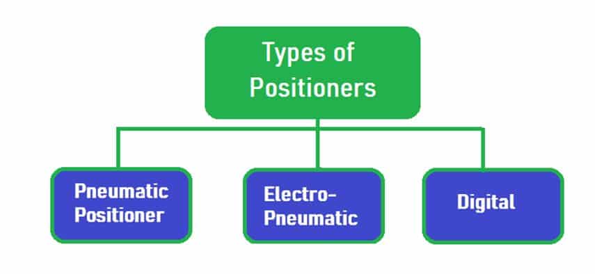
Pneumatic Control Valve Positioner
The Pneumatic positioners use input signals 3-15 PSI (pounds per square inch), although others other input signals we can use, depending on the process.
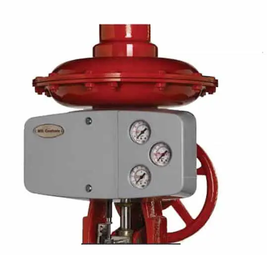
They are typically used in combination with an i/p transducer that converts an electrical signal to a pneumatic one.
The configuration of electrical signals for the site is not safe for the potentially explosive atmosphere. The pneumatic signal is the safest where it is essential to minimize the risks of handling electrical signals. Therefore, an electrical signal is converted into a pneumatic signal by an I/P converter for site use.
Electro-pneumatic Control Valve positioner
Electro-pneumatic positioners have widespread applications in the process industry. Its pneumatics and mechanics are similar to those of pneumatic positioners.
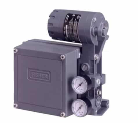
The electro-pneumatic positioner controls the gradual opening of valves in conjunction with pneumatic actuators. Pneumatic pressure and 4 to 20 mA electrical signal through electronic controller gradually opens the valve. For a rotary actuator, the turning position of the actuator is between 0 degrees and 90 degrees.
However, electro-pneumatic positioners have a directly attached upstream converter module. It converts the reference input from an electrical signal (4 to 20 mA) to a pneumatic signal between 0.2 and 1 bar.
Digital Control Valve positioner
Digital positioners connect the control system to the valve. A microprocessor controls
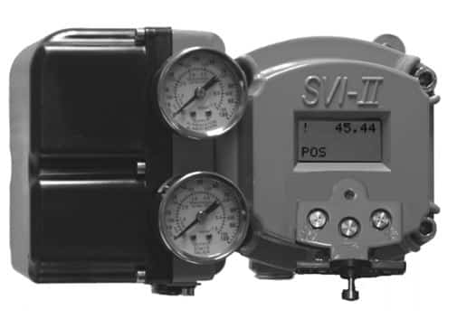
Available communication profiles include Foundation Fieldbus (FF), HART protocol, and Profibus PA. Positioners that receive a 4-20mA signal or digital signal (protocol-based devices), for example, HART and position the valve based on the input signal and give feedback to the controller. At the same time, we can configure fail-safe conditions and direct or reverse acting mode.
Advantages of digital positioners
Digital positioners are more advanced than any other type of positioners. The followings are the advantages of the digital positioners.
- Reduced air consumption.
- Automatic start-up (zero and span adjustment).
- Continuous supervision of the control loop.
- Adjustable control speed.
- Digital communication via HART protocol, Foundation Fieldbus, Profibus.
- Improved control valve reliability and performance.
- More accurate calibration for more precise control.
- Advanced diagnostics for predictive maintenance.
The main reason for the popularity of digital positioners is that they can do much more than control valve positions.

Read Next:
dear sir,
The electro-pneumatic positioner controls the gradual opening of valves in conjunction with pneumatic actuators. Pneumatic pressure and 4 to 20 mA electrical signal through electronic controller gradually opens the valve. For a rotary actuator, the turning position of the actuator is between 0 degrees and 90 degrees.
However, electro-pneumatic positioners have a directly attached upstream converter module. It converts the reference input from an electrical signal (4 to 20 mA) to a pneumatic signal between 0.2 and 1 bar.