We use a 4-20 mA current signal instead of a voltage signal because the current signal has numerous advantages. In this article, we will discuss in detail what is the voltage signal & current signal.
We can transmit an electrical signal in the form of voltage or current from one end to another end. The transmission of the current signal has many advantages over the voltage signal transmission. Let’s first understand what are the features of the current & voltage signal.
Voltage Signal
The voltage signal at the receiving end might be somewhat less than the signal magnitude at the sending end. The main reason for this difference in sending end and receiving end voltage is the voltage drop in the transmission medium (cable).
The cable has a certain value of resistance /meter. The longer the length of the cable, the more is its resistance. And finally, the larger resistance contributes to more voltage drop across the cable.
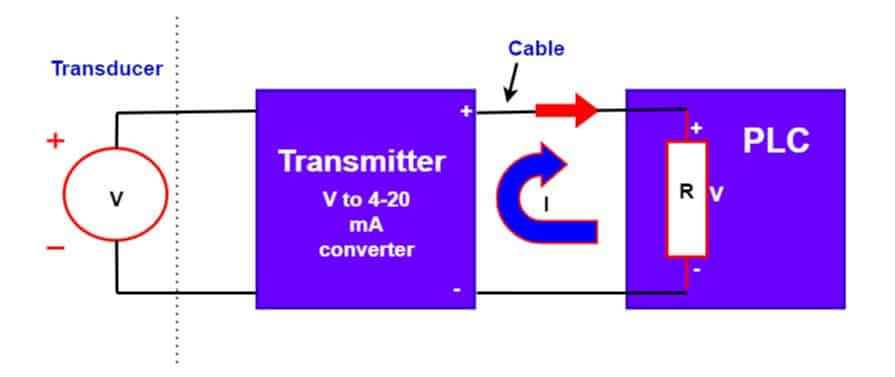
The voltage signal when transmitted over a long distance it causes a voltage drop in the wires. We can understand this with the following electric circuit.
Here,
Vs -Sending end Voltage
VR – Receiving end voltage
RL = Cable leads resistance ( For entire circuit)
R = Terminating resistance at the PLC end
I = Current in Circuit
Current flowing in the circuit
I = Vs/(RL+R)
Voltage drop in the cable
v = I x RL
Thus, the voltage drop increase with an increase in cable length and it causes less voltage at the receiving end. The difference in the sending end and the receiving end voltage leads to an error in measurement.
This is one of the reasons why the voltage signal is not used for signal transmission.
It is desirable that the signal produced at the receiving end must be distortion-free. The electromagnetic interference can superimpose on the voltage signal, and the signal received at the receiver end has distorted voltage. Thus, it causes errors in the measurement.
The response time of the voltage signal is slow compared to the current signal. The line capacitance & inductance causes the slow response of the voltage signal.
The impedance of the voltage source is always more than the impedance of the current source. The noise immunity depends on the source impedance. The larger the source resistance, the lesser is the noise immunity. Thus, the voltage source has less noise immunity & it is prone to pick up the noise.
We can summarize the reasons for not using the voltage signals.
- Voltage drop
- Prone to interference
- Slow response
- Less measurement linearity
- Low noise immunity
- Risk of fire due to sparking
Now, we will see why there is no measurement error when we use the current signal.
Current Signal
As shown in the below diagram, the current remains the same in a close loop of an electric circuit.
The current at the sending and receiving end remains the same. The current can not divert in a closed path. Thus, when we use a current signal for long-distance transmission, the current in the entire circuit remains the same.
The measuring accuracy of the instrument working on the current signal is much better than the instrument working on the voltage sensing principle.
For signal transmission from the transmitter to PLC, we can either use a 0-20 mA signal or a 4-20 mA signal for long-distance transmission. The transducer converts physics quantities like pressure, temperature and pressure into a voltage signal. Further, the transmitter converts the voltage signal into the current signal & then, the current signal is sent to the central control room, PLC, or DCS station.
Thus, the current signal is the best for signal transmission. To summarize, the following are the advantages of the use of the current signal.
- No voltage drop issue
- No interference with electromagnetic waves
- Fast Response
- High noise immunity
- Good measurement linearity
- Suitable for long-distance signal transmission( up to 1 KM)
- No electric spark- No risk of fire
Why is the 0-20 mA current signal not used?
The transmitter can output a 4-20 mA or 0-20 mA signal. However, we do not use a 0-20 mA signal. A 0-20 mA signal transmission means if the current is zero, the process value is zero. However, in the case of a fault in the transducer, transmitter, or cable the current is zero. Thus, in this condition, we can not say whether the process value is zero or fault in the measuring system. The zero value of current even appears when the cable is open.
Thus, the 0-20 mA signal is not a fail-safe. Therefore, a 0-20 mA current signal is not used.
Why is a 4-20 mA current signal a good choice?
If you use a 4-20 mA current signal, the broken wire or instrument failure is easy to detect. In normal operation, the output of the transmitter is 4 mA when the process value is zero. In the case of wire open or instrument failure, the output current drops to zero. Thus reduction of current from 4 mA to 0 mA indicates there is something wrong with the measurement system. The transmitter outputs an alarm when the current drops to zero value.
The transmitter which has a 4-20 mA current output feature receives loop powered 24 volts DC supply. We call the transmitter with this feature a 2-wire transmitter. The electronics circuitry draws current from a 24 volts DC supply for its operation and simultaneously outputs the current according to the process value.
Thus, when the process value is zero, the loop current is 4 mA. If the process value is maximum, then the loop current is 20 mA.
The loop-powered 24 volts DC transmitter scheme is given below.
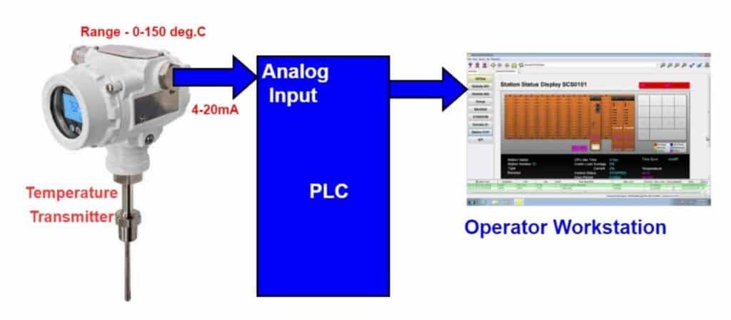
The 4-20 mA corresponding to process temperature is fed in 250 ohms resistance connected to the transmitter circuit. The resistor converts the current signal into a voltage signal. Further, the analog input module of PLC converts the analog voltage signal into a digital signal.
Read Next: