The main characteristic of an electrical system is its waveform which, under all operating conditions and load conditions, must always remain a pure sine wave. Factors altering this sinusoidal wave shape can be said to be affecting the power quality within the electrical system.
The level of harmonics in present day electrical network is steadily increasing due to the introduction of energy efficient power electronics loads, usually referred to as non linear loads. These non linear loads despite being energy efficient, pollute electrical network with harmonics, causing degradation of power quality which in turn affects performance of other electrical equipment within the same network, In extreme cases, the harmonics introduced by non linear loads is sufficient to cause total failure and breakdown of the equipments.
In addition to this, the use of power factor correcting capacitors further complicates the entire scenario. Although capacitors themselves do not generate harmonics, they interact with the existing harmonics in the network and the network impedance causing a phenomenon called ‘ Resonance’. The use of power capacitors however, is rapidly growing due to the severe penalties levied by electrical utilities if consumers operate their network at low power factor levels.
In addition to this, the use of power factor correcting capacitors further complicates the entire scenario. Although capacitors themselves do not generate harmonics, they interact with the existing harmonics in the network and the network impedance causing a phenomenon called ‘ Resonance’. The use of power capacitors however, is rapidly growing due to the severe penalties levied by electrical utilities if consumers operate their network at low power factor levels.
Ironically, a network without any non-linear load can also have harmonic problems since electrical network can import harmonics from the main supply grid. This is frequently observed Indian conditions where the supply grid itself is polluted with harmonics introduced by various consumers. In cases where harmonics are present at the main supply level, the overall power quality within the network is low and the use of power capacitors in such scenario can also lead to resonance. The problem experienced in such clean network is similar to the problems experienced in networks containing many non-linear loads.
It is commonly observed that harmonics exist at varying levels in almost all electrical networks, and the uses of conventional power factor correction capacitors tends to cause the undesirable phenomena of resonance which further aggravates the entire problem.
COST RELATED TO HARMONIC POLLUTION IN ELECTRICAL NETWORK
Cost implications of the ill- effects of harmonics can be classified on the following basis for its better understanding.
Direct Cost
Direct cost arises from increased energy consumption due to higher losses and result in inflated energy cost. These increased energy losses occurs because the resistance of all current carrying components increased at higher harmonic frequencies due to skin effect. Due to phenomenon of skin effect, all the current carrying components exhibit higher I2R losses. Energy consumption also increases in equipments like motors, transformers etc.
Indirect Cost
There are several indirect cost associated with presence of harmonics in the network. The indirect cost components can be classified as under.
A) Maintenance costs
Harmonic pollution in electrical networks causes several problems. Use to this, the maintenance activity to be carried out on various equipments increase, causing additional maintenance costs. For example, the insulation of motor degrades due to excessiv3 heating caused by flow of harmonic currents and can cause premature failure. They have to be frequently rewound increasing the maintenance costs.
B) Down time costs
Equipments tend to fail more often in electrical environment polluted with harmonics. All these failures result in loss of production due to increased down time. The financial loss associated with down time depends on the nature of the industry, with cost being highest for continuous process industries like petrochemical or cement.
D ) Equipment replacement costs
In certain cases, high level of harmonics in electrical network cause total breakdown of equipment (example sensitive PLC card, electronic devices etc). As a result, the damaged equipment has to be replaced, imposing a high replacement cost.
E) Equipment derating cost
When harmonic are present in an electrical network, equipments connected to it must have a certain immunity level to harmonics in order to perform normally. One method of increasing immunity levels of equipment is derating.
It is interesting to note at this stage, the guidelines specified by the new IEC 61000-2-4.according to this standard, electrical networks are classified according to the level of harmonic voltage distortion under which they operate. The classifications are as under.
1) Class 1- upto 5% total harmonic distortion in voltage
2) Class 2- upto 8% total harmonic distortion in voltage
3) Class 3- upto 10% total harmonic distortion in voltage
The user of the electrical network has to be declare his class of installation, based upon the above permissible distortion in his network, and procure electrical equipment suitable to operate under such an environment. Thus class 3 users have to ensure that his electrical equipment tolerates a distortion level of 10%. Such harmonically immune equipment would be more expensive compared to class 1 category equipment. Thus, the presence of higher harmonic distortion requires equipment with higher investment contributing to higher indirect costs.
SAFETY COST
Ensuring electrical safety in a network is a paramount requirement of any designer or consultant. Ensuring this safety in the presence of harmonic distortion calls for better understanding of this situation and involves additional cost component. This safety criterion is extremely important in modern buildings whether commercial or residential.
‘Triplen harmonics’ are a special category of harmonics with frequencies equal to odd multiples of three like 150Hz,450Hz etc. theses harmonics tend to flow in the neutral since they are zero sequence in nature.
Triplen harmonics are generated by single-phase SMPS driven loads like computers, televisions and other office equipment’s. In installations where such loads are abundant, like IT parks, modern buildings etc. the magnitude of the neutral current can be higher than the line currents. Conventionally designed neutral conductors subject to such conditions get overheated, causing fire hazards. There is also a risk of the neutral being open circuited causing dangerous voltages across single-phase equipment. This can cause total failure of the equipment and also poses a serious risk to life of operating personnel.
HARMONIC “EMISSION- compatibility- Immunity “ levels
The application international standards for industrial & non-public power distribution system up to 35 KV are the IEC 61000-2-4. It is important to note that the second edition of this standard was issued in June 2002 with a specific mention in the foreword that it is applicable without changes until 2010.
Further this standard defines ‘compatibility ‘ level as the specified electromagnetic disturbance level used as reference level in a specified environment for co-ordination in the setting of emission and immunity limits.
This compatibility level is generally chosen such that there is only a very low probability that it will be exceed by the actual disturbance level. In this context it is necessary to plan the design and operation of the power supply network in the relevant area. This compatibility level is generally applicable at the in-plant point of coupling-IPC. The IPC is that point on a network installtion, electrically closest to a particular load, at which other loads are, or could be, connected. The IPC is different from the point of common coupling i.e., PCC which is the specific point defined on a public power supply network.
The modern approach is to categorize all electro magnetic environments i.e. electrical installations, into specified classes. The various classes are specified under clause 4 of this IEC standard. The compatibility levels for harmonics in each class are specified in clause 5 of this standard. It is thus necessary to ensure that the emission level of harmonics must be with in the compatibility levels. In case the emission levels exceed the compatibility levels mitigation is necessary to bring the harmonic levels within the compatibility levels.
It is in this context that the concept of immunity levels must be viewed. Various products used with in the power system are susceptible to malfunction/failure if their immunity limits are incompatible with the applicable compatibility levels. Hence immunity limits must always be viewed in the context of product standards as well as compatibility levels.
The recommended approach towards achieving “ Compatibility “ levels consists of one or more of the following actions:
- Increase Immunity levels
- Decoupling of circuits
- Decrease the emission levels
HARMONIC MITIGATION SOLUTIONS
It is sufficiently clear that harmonics are to be mitigated to ensure reliable and cost-effective operation of electrical networks. There are several techniques that can be employed to reduce harmonic levels in electrical networks. Broadly, each harmonic mitigation solution must provide the following benefits:
1) Reduce harmonics in the network to a desired level
2) Provide the required capacitive kVAr to improve power factor to a desired target value. This function is analogous to the function of a conventional power factor correcting capacitor.
3) Prevent the occurrence of series or parallel resonance
It is interesting to note the following concept, which forms an important basis of harmonic filter design.
As loads are dynamically varying, capacitors also vary so as to maintain desired power factor at various locations in the network. Thus the equivalent inductive reactance and capacitive reactance of the network varies continuously and becomes equal at a particular frequency, causing resonance at that frequency. If harmonic components generated by non-linear loads in the network coincide with this frequency, resonance occurs resulting in amplification of harmonic currents in the networks.
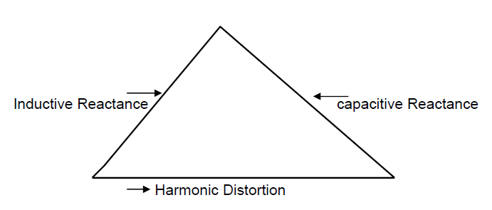
The concept of harmonic amplification can be understood by the figure shown above. The three ingredients of harmonic amplification are depicted as three sides of the triangle. Eliminating any one of them form the network results in minimizing the risk of harmonic amplification.Elimination of harmonic distortion in total is not possible in the presence of several non-linear loads existing in present day networks. Logically, it is true that if we remove the non-linear load then there will be no harmonics and therefore all related problems will be eliminated.
Next, thinking of inductance to be removed is not a practical solution as it means to avoid the use of transformers, induction motors and even bus bars as it contributes to inductance. Hypothetically, even if we assume that removal of inductance is possible, resonance cannot occur, herby avoiding harmonic amplification.
Lastly, it means the only plausible way to avoid harmonic amplification is to remove capacitors, which means power factor correction cannot be achieved. This also means that capacitors cannot be eliminated from electrical networks.
From the above, it is clear that practically, harmonic distortion and inductive impedance from an essential part of all modern day networks and cannot be eliminated. Therefore, how do we manage a network in which the entire three elements co-exist? The answer is to have a suitable device that behaves like a capacitor at the fundamental frequency (where power factor correction is required) and behaves like an inductance at harmonic frequencies to avoid amplification of harmonics due to resonance.
This, in essence, is the origin of the underlying concept in the development of harmonic filtering.
It is however a fact that due to the growing diversity in the nature of loads and changing characteristics of network it has become to decrease the emission levels and thereby achieves compatibility level.
The approach to decrease emission levels involves two sub approaches. They are
- Select such equipment which has lower emission level for example
a) Use a 12 pulse converter instead of 6 pulse converter
b) Use UPS systems with inherently low emission levels
- Install equipment to filter the harmonics and thus achieve compatibility level
The desired filtering of harmonics can be achieved by applying one or more of the following types of filters:
- Passive filter
- Active filter
- Hybrid filter
It is in this context that the concept of immunity levels must be viewed. Various products used with in the power system are susceptible to malfunction/failure if their immunity limits are incompatible with the applicable compatibility levels. Hence immunity limits must always be viewed in the context of product standards as well as compatibility levels.
The recommended approach towards achieving “ Compatibility “ levels consists of one or more of the following actions:
- Increase Immunity levels
- Decoupling of circuits
- Decrease the emission levels
HARMONIC MITIGATION SOLUTIONS
It is sufficiently clear that harmonics are to be mitigated to ensure reliable and cost-effective operation of electrical networks. There are several techniques that can be employed to reduce harmonic levels in electrical networks. Broadly, each harmonic mitigation solution must provide the following benefits:
1) Reduce harmonics in the network to a desired level
2) Provide the required capacitive kVAr to improve power factor to a desired target value. This function is analogous to the function of a conventional power factor correcting capacitor.
3) Prevent the occurrence of series or parallel resonance
It is interesting to note the following concept, which forms an important basis of harmonic filter design.
As loads are dynamically varying, capacitors also vary so as to maintain desired power factor at various locations in the network. Thus the equivalent inductive reactance and capacitive reactance of the network varies continuously and becomes equal at a particular frequency, causing resonance at that frequency. If harmonic components generated by non-linear loads in the network coincide with this frequency, resonance occurs resulting in amplification of harmonic currents in the networks.
Related Posts on Harmonics
- Harmonics and Harmonic Frequency in AC Circuits
- Difference between Harmonics and Sub-Harmonics
- Interharmonics in Power System
- Effects of Harmonics on Transformers
- Effects of Harmonics on Capacitors | Interaction of Harmonics with Capacitors
- Effects of Harmonics on Power Cables
- Impact Of Harmonics On Induction Motor
- Adverse Effects Of Harmonics On Electrical Equipments
- Impact Of Harmonics On Power Quality
- Working Principle of Active Harmonic Filter
- Neutral Conductor Size Selection For Non Linear Loads