Harmonics in induction motors adversely affects motor performance, leading to temperature rise and increased losses, decreased torque, and noise problems.In VFD-fed systems, harmonics distort waveforms and increase losses.
This article explains what harmonics are, how they affect induction motors, and practical methods to reduce harmonic distortion in motor systems.
How VFDs Affect Induction Motors
Due to simplicity in construction and ease of operation and maintenance, induction motors have become the most popular prime mover, and about 80 % of the electrical drives are induction motors. An induction motor will perform best if the perfect sinusoidal voltage is fed to the induction motor.
V = Vm x sinϕ
Today, variable frequency drives (VFDs) are widely used in industries. They allow efficient and accurate speed control.
VFDs use semiconductor devices to convert input sinusoidal voltage to DC and again to a regulated variable voltage/ variable frequency. Their inverter and converter sections contain semiconductors like diodes and IGBTs.
These semiconductor devices show non-linear characteristics in voltage and current.
As a result, they introduce harmonic currents into the system, which severely impacts induction motor performance.
How Harmonics Are Introduced in Induction Motors
Harmonics in induction motors originate from non-sinusoidal voltage sources like VFDs. These sources introduce odd harmonics such as the 3rd, 5th, and 7th, which disrupt motor operation.
When supply to the induction motor is fed from an inverter or cyclo-converter, the motor terminal voltage is non-sinusoidal but has half-wave symmetry.
A non-sinusoidal waveform can be resolved into fundamental and harmonic components using Fourier analysis. Because of the half-wave symmetry of the inverter output, only odd harmonics will be present.
Fundamental Phase Voltages (ABC phase sequence):
VAN = V1 sin(ωt)
VBN = V1 sin(ωt – 2π/3)
VCN = V1 sin(ωt – 4π/3)
The corresponding 5th and 7th harmonic phase voltage is
5th Harmonic Phase Voltages:
VAN = V5 sin 5wt
VBN = V5 sin (5wt – 4𝝅 /3 )
VCN = V5 sin (5wt –2𝝅 /3)
The 5th harmonic has a negative sequence (ACB phase order). hence, it is a negative phase sequence harmonic.
7th Harmonic Phase Voltages:
VAN = V7 sin 7wt
VBN = V5 sin (7wt – 2𝝅 /3 )
VCN = V5 sin (7wt –4𝝅 /3)
The 7th harmonic has a positive sequence (ABC phase order), same as the fundamental.
In delta-connected motors, triplen harmonics (3rd, 6th, 9th, etc.) circulate within the delta winding and are not seen at the source end, but they still cause internal heating and losses.
The motor’s phase current under harmonic influence is expressed as:
I2 rms = I2s + ∑ I2m
m=3,5…
With harmonic current, the motor’s RMS current is higher than the fundamental current. The increased current due to harmonics increases the copper loss substantially.
The core loss also increases because of harmonic currents.
Because of increased losses, the motor need to de-rated because the power output obtained from the machine for the same temperature rise has to be smaller.
The efficiency is also reduced due to an increase in losses.
Another important effect of non-sinusoidal supply is the production of pulsating torque due to the interaction between the rotating field produced by one harmonic and the rotor current of another harmonic.
Harmonics orders 5, 7, 11, and 13 significantly contribute to torque pulsations. 5th harmonic produces a backward rotating field, and the 7th harmonic produces a forward rotating magnetic field.
As a result, the relative speed between the field produced by the fundamental and 5th and 7th harmonic current is six times the speed of the fundamental.
The same case is with the harmonics orders 11 and 13 that produce torque pulsation whose frequency is 12 times more than that of fundamental.
When the motor supply frequency is low, these torque pulsations cause pulsation in speed.
Effects of Harmonics in Motor
The presence of harmonic distortion alters key motor parameters such as torque, losses, noise levels, and overall reliability.
Harmonics can cause serious performance degradation in induction motors. The most critical effects include:
- Variation in Torque-speed characteristics
- Reliability Issues
- Torque Reduction
- Cogging and Crawling in motor
- Noise and vibration
- Decreased Efficiency and Temperature rise
- Higher losses due to Skin effect
- Stress on the first turns of the motor winding
Torque-Speed Curve Deviation Due to Harmonics
The motor should accelerate the load and continue to output the mechanical power demanded by the equipment.
The harmonics in the motor deviate the torque-speed characteristics from its destined curve and negatively impact the motor performance.
Reliability Issues Caused by Harmonic Heating
The induction motor’s reliable operation depends on the insulating material’s life. The insulation resistance decreases as the temperature is increased.
The harmonic current has a higher frequency, and because of higher frequencies of harmonic current, the eddy current and hysteresis losses increase, leading to the rising of core temperature.
The shaft voltage may also be set up because of increased stray capacitance at higher-order harmonic current.
The higher shaft current may cause the bearings to fail. The bearing of the motor’s non-driving end(NDE) side must be insulated, or the shaft must be grounded through the carbon brush.
Read: Why Insulated Bearing is used for VFD driven Induction Motor?
Torque Reduction Due to Harmonic Losses
The torque of the machine depends on the rotor input power.
Rotor Input power = Stator Input power – Power losses
Harmonic distortion causes increased losses in motors in the same way as in transformers. However, additional losses arise due to the production of harmonic-generated fields.
Each harmonic has a sequence of positive (+), negative (-), and zero (0) sequences that indicate the direction of rotation that would result if it were to be applied to an induction motor with respect to the fundamental.
| Harmonic Order | 1 | 2 | 3 | 4 | 5 | 6 | 7 | 8 | 9 | 10 | 11 | 12 |
| Phase Sequence | + | _ | 0 | + | _ | 0 | + | _ | 0 | + | _ | 0 |
Zero sequence harmonics (3, 6, 9, 12), the third, and multiples of the third (Triplen) produce a stationary field. Still, since the harmonic field frequencies are higher, the magnetic losses are significantly increased, and the harmonic energy is dissipated as heat.
Negative sequence harmonics result in a counter-rotating field with respect to fundamentals, which results in reduced torque.
Positive sequence components produce a forward rotating field that adds to the torque.
The positive and negative sequence torque components result in vibration and reduce the service life of the motor.
Table: Effects of Specific Harmonic Orders on Motor
| Harmonic Order | Sequence Type | Effect |
|---|---|---|
| 3, 6, 9 | Zero | Stationary field, increased heating and losses |
| 5 | Negative | Counter-rotating torque, torque dip, cogging |
| 7 | Positive | Forward field, crawling issues |
| 11, 13 | Mixed | High-frequency torque pulsation, vibration |
Cogging and Crawling from 5th and 7th Harmonics
The 5th and 7th harmonics order current produces a resultant flux distribution in the air gap that can cause a phenomenon called cogging( Refusal to start smoothly or crawl ( run at very high slip ).
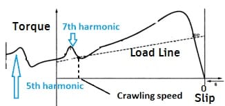
The synchronous speed of the motor is different for different order harmonics.
When the motor accelerates, the base speed synchronous speed has to go through the synchronous speed of harmonics.
If the load torque is met with the synchronous torque produced with the 7th-order harmonics, the motor speed will increase to 1/7th of the base speed. This phenomenon is known as crawling.
Read detailed Article on: Cogging and Crawling in Induction Motor
Noise and Vibration Effects from Harmonics
The noise due to asynchronous and synchronous torques is most evident during starting.
The vibratory forces are caused when the number of pairs of poles of higher harmonic fields in the stator and rotor differs by 1.
Magnetic pull is set up in a certain direction, and this travels around the machine, tending to make the stator-rotor oscillate.
If the pole pairs differ in numbers by more than one, several unbalanced radial forces will travel around the rotor and cause vibration and noise.
The higher-order harmonics current produces the audible noise in the motor.
Efficiency Loss and Temperature Rise in Motors
A significant effect of harmonic voltage and current in the motor is increased heating due to increased iron and copper losses at the harmonic frequencies.
This affects the machine’s efficiency and temperature rise.
Due to harmonic, both copper and iron losses increase because both the losses are frequency dependent.
Increased Resistance from Skin Effect
The current tends to flow at the outer surface of the conductor with an increased frequency, a phenomenon known as the SKIN EFFECT.
The harmonic current has a higher frequency and flows at the outer surface of the conductor.
As a result, the effective area of the conductor gets reduced, and the resistance of the conductor gets increased because the resistance is inversely proportional to the cross-section area of the conductor.
The higher resistance leads to higher copper loss( I2R Loss).
Voltage Stress on Stator Winding from Harmonics
The IGBT PWM inverter fed the voltage to the motor’s stator. The motor receives non-sinusoidal voltage with a high rate of rise voltage( dv/dt) coupled with harmonics.
This may lead to uneven voltage distribution in the stator winding, and the voltage of the first few turns of stator winding may rise to 2.5 times the motor’s rated stator voltage.
The higher voltage stress on the first few turns on the motor may cause insulation failure.
In conclusion, the harmonics in the motor cause higher losses and deteriorate its performance.
How to Reduce Harmonics in Induction Motor
You can minimize harmonics in induction motors by following these methods:
- Install passive harmonic filters (e.g., trap filters for 5th or 7th order)
- Use active harmonic filters to dynamically cancel harmonic distortion
- Apply multi-pulse rectifiers (like 12 or 18-pulse converters)
- Use K-rated transformers in nonlinear load environments
- Avoid resonance conditions with proper tuning of capacitors
- Oversize neutral conductors for systems with high harmonic content
- Conduct power quality audits using harmonic analyzers
Conclusion
Harmonics in induction motors significantly affect performance, reliability, and efficiency.
They distort the voltage and current waveforms, leading to increased losses, reduced torque, overheating, and mechanical stress.
Critical issues like cogging, crawling, vibration, and higher temperature rise are direct results of harmonic distortion—especially from 5th and 7th order harmonics.
To ensure optimal motor operation and extended lifespan, it’s essential to identify harmonic sources and apply mitigation techniques like using filters, harmonic-friendly drives, and proper grounding.
Addressing harmonics is not just a power quality measure—it’s a necessity for maintaining motor health and energy efficiency in modern electrical systems.
FAQs – Harmonics in Induction Motor
Harmonics refer to voltage or current components at multiples of the fundamental frequency that distort the waveform and affect motor operation.
Harmonics increase losses, heat, and noise while reducing torque and overall efficiency.
You can use harmonic filters, K-rated transformers, multi-pulse rectifiers, and ensure proper tuning of capacitor banks.
Related Article:
Very informative post indeed!! It helps in better understanding of the scenario occurring in induction motors!!!thanks
Informative, Concise and Understandable