In this article, we will discuss the procedure of pressure transmitter calibration. Pressure transmitters are used to measure the pressure on any line, vessel, or any other equipment in the plant. Before moving ahead in this article, have a look at the Basics of Pressure Measurement.
Pressure measurement is very important in every plant. Hence, pressure transmitters should be calibrated at proper intervals to ensure they are working properly. Any error in measurement can lead to plant trips and unnecessary process interruptions and many a times disasters as well.
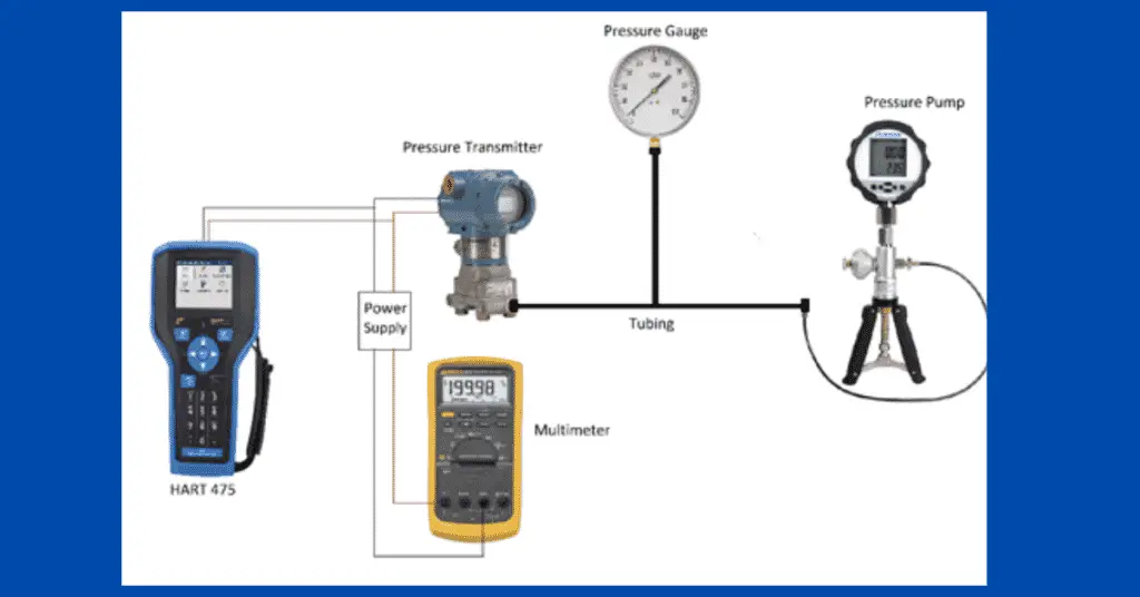
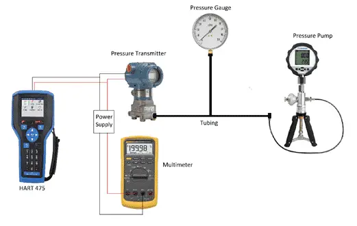
For doing the calibration of a pressure transmitter following equipment is required.
- Pressure transmitter to be calibrated
- Pressure pump
- A calibrated pressure gauge of an appropriate range
- Power supply (if the pressure transmitter is not connected to the system and needs an external power supply)
- Multimeter
- HART
Pressure Transmitter Calibration Procedure
Let us now discuss the pressure transmitter calibration procedure.
The following steps are required to be followed for pressure transmitter calibration.
Step-1
The pressure transmitter to be calibrated should be either powered on through the cables which connect it to the system or external power supply.
Step-2
If the pressure transmitter is in the field, isolate the pressure transmitter. Flush the pressure transmitter in a closed drain if used in hazardous chemicals.
Step-3
Connect the multimeter in a series configuration. Do not forget to connect the leads to mA and the common terminal on the multimeter. Many times, we fail to change the lead configuration in the multimeter.
Step-4
Now connect the pressure transmitter to the hand pump by using proper tubing. Do not use PU tubing if the pressure range is high. PU tube may burst at high pressures. The pressure generating a range of the hand pump should be greater than that of the pressure transmitter’s range.
Step-5
Connect a pressure gauge to the tubing connecting the hand pump and the transmitter. The extra pressure gauge is used to avoid errors sometimes caused in the pressure pump display.
Step-6
You need the range of the pressure transmitter’s range which is used in the field. A datasheet can show you the range of the sensor. From range you know the 0% value and 100% value. Calculate 25% value, 50% value and 75% value from it. Suppose range is from 0 kg/cm2 to 10 kg/cm2, then 0 kg/cm2 is 0% value and 10 is 100% value. 2.5 kg/cm2 is 25% value, 5 kg/cm2 is 50% value and 7.5 kg/cm2 is 75% value.
Step-7
Apply 0% value from the hand pump (if 0% is greater than 0 kg/cm2). Check for any leakages. Also, observe the pressure. Pressure should remain steady. If pressure is dropping then there is leakage in the system. Identify the leakage and arrest it. After that check the readings on the display of the pressure pump and the pressure gauge. Both should be matching. If the mismatch is there, then try replacing the pressure gauge. If a still mismatch is present, try replacing the display of the pressure pump.
Step-8
Similarly check and note down the values for 25% value, 50% value, 75% value and 100% value. Now check for 75% value, 50% value 25% value and 0% value. Remember to keep checking for leakages after increasing the pressure every time. It is always good practice to plot a graph of upward readings and downward readings we got from the procedure we followed. This helps to know the hysteresis of the pressure transmitter we are using.
Step-9
Now calculate the error% from the values noted down in the above steps. If the error we obtained is within the acceptable limits as per the datasheet, then the pressure transmitter is ok. If the error is more than the maximum error permissible as per the datasheet then zero and span calibration is needed.
Step-10
If an error is greater than the maximum permissible error, then first apply the 0% value and check whether it is ok or not. If it is not ok, then connect the HART and apply zero trim. Now the transmitter should show the exact 0% value.
Step-11
Now check the 100% value by applying the pressure. If it is ok, then move to Step 6. If it is not ok, then apply span trim from the HART. After applying the span trim, the transmitter should show the exact 100% value. Now move to step 6 and again repeat all steps.
Step-12
Remove multimeter, HART, and pressure pump tubing from a pressure transmitter.
Step-13
Now take the pressure transmitter in line.