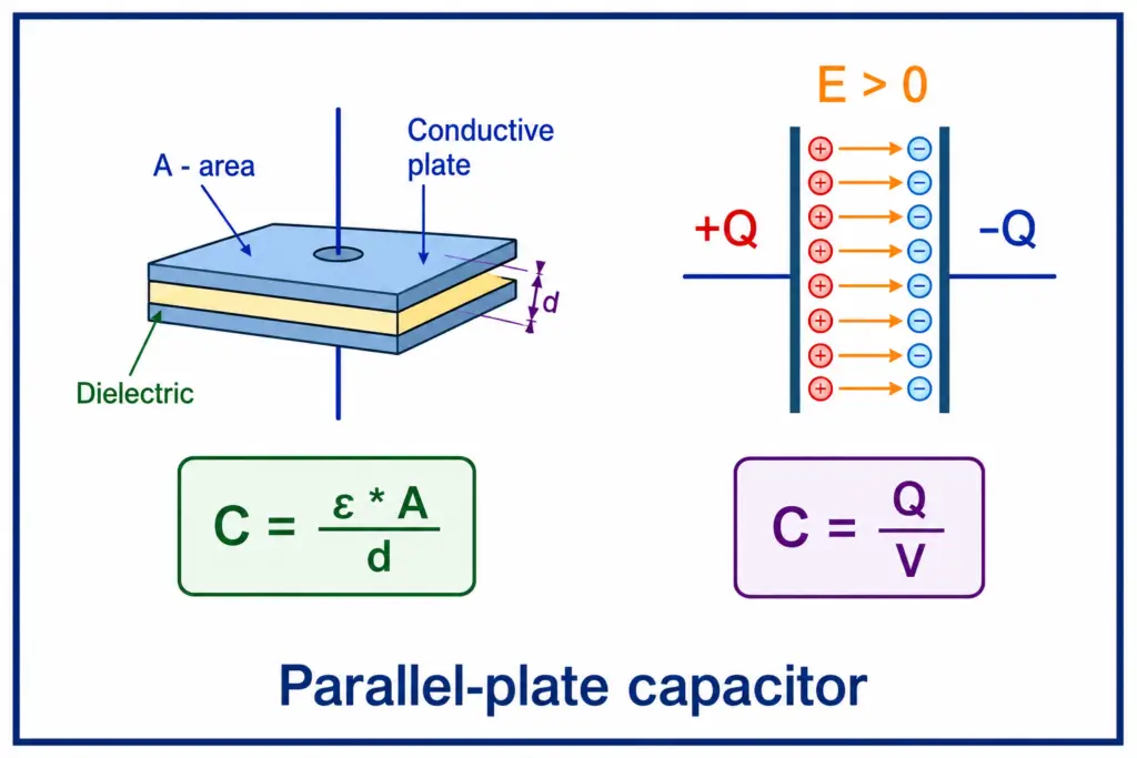
A parallel plate capacitor has two conductive plates placed parallel to each other and separated by a certain distance. It has a dielectric medium between the plates and stores energy in the form of an electric field.
A capacitor is one of the basic electronic circuit elements used in a variety of electrical and electronic circuits. A capacitor is a device that can store electrical energy in the form of an electric field. Based on the construction, there are several different types of capacitors.
In this article, we will discuss the definition, construction, and step-by-step derivation of the capacitance formula for a parallel plate capacitor. We will also explain the capacitance calculation of a parallel plate capacitor with practical examples.
Core Formula: C = (ε0 εr A) / d
Key Variables: A (Area of each plate), d (Separation distance), ε0 (Permittivity of free space), and εr (Relative permittivity of the dielectric).
Primary Function: To store electrical energy in an electrostatic field for applications in filtering, tuning, sensing, and energy storage.
What is a Parallel Plate Capacitor?
A parallel plate capacitor is constructed by placing two metal plates parallel to each other and separated by an insulating medium.
It is the simplest type of capacitor. The typical construction diagram of it is shown in the following figure:
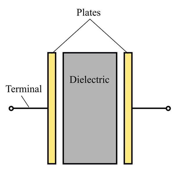
It has two metal plates and an insulating medium between the plates. The insulating medium is a dielectric material that can store electrical energy in the form of an electrostatic field. Some commonly used types of dielectric materials are air, mica, wax paper, etc.
Parallel Plate Capacitor Formula
The capacitance of a parallel plate capacitor is;
- Directly proportional to the area (A) of each plate.
- Inversely proportional to the distance (d) between the plates.
- Directly proportional to the permittivity of the dielectric medium.
Therefore,
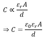
Where ε0 is the dielectric constant of air, εr is the dielectric constant of the medium between the plates.
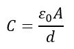
For an air capacitor, εr = 1, therefore, the capacitance of an air capacitor is given by,
The capacitance of a parallel plate capacitor depends on three factors: the plate area (A), the distance between the plates (d), and the permittivity of the dielectric medium (εᵣ). Increasing the plate area or dielectric constant increases the capacitance, whereas increasing the plate separation decreases the capacitance. Therefore, the capacitance calculation of a parallel plate capacitor is performed using the above formula by substituting the values of A, d, ε₀, and εᵣ.
Construction of Parallel Plate Capacitor
A parallel plate capacitor is simply constructed by separating two parallel metal plates by a dielectric medium.
Parallel plate capacitors can be constructed in the following two ways:
- Capacitor with Uniform Dielectric Medium
- Capacitor with Composite Dielectric Medium
Let us now discuss each construction in detail along with their capacitance computation.
(1). Parallel Plate Capacitor with Uniform Dielectric Medium
A capacitor with a uniform dielectric medium is shown in the following figure.
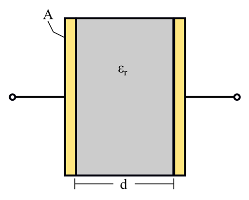
It consists of two metal plates, each of surface area A, and these plates are separated by a uniform dielectric medium of thickness d. If the relative permittivity of the dielectric medium is εr, then the capacitance of the capacitor is given by,
(2). Parallel Plate Capacitor with Composite Dielectric Medium
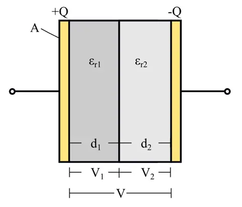
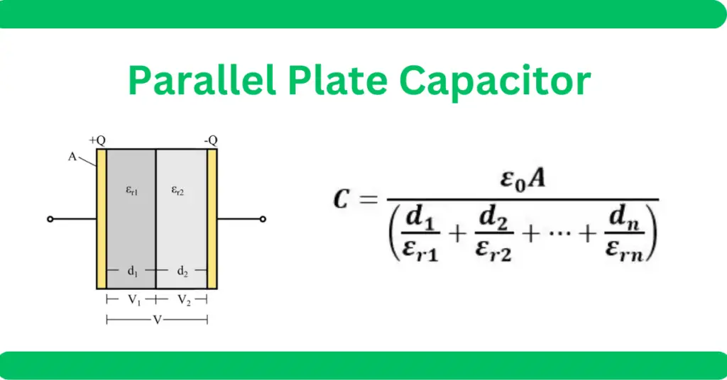
In this type of construction, different dielectric mediums are placed between the plates of the capacitor. The following figure shows a parallel plate capacitor with two dielectric mediums with two different relative permittivities, i.e. εr1 and εr2 respectively.
Parallel Plate Capacitor Formula Derivation (Composite Dielectric)
To understand how multi-layered insulation works, we perform a step-by-step derivation of the parallel plate capacitor formula. This derivation accounts for varying dielectric constants (εr1 and εr2 in a composite medium, which is essential for accurate capacitance calculation.
For this type of capacitor, we can derive the capacitance formula as follows:
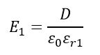
Step 1: Electric Field Intensity Calculation
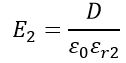
The electric field intensity in the two dielectric fields is given by,
And,
Step 2: Relate to Charge Density
We use the surface charge density (D), which remains constant across both dielectric layers because the total charge (Q) per plate is the same (Q coulombs). It is expressed as:

It is the same for both dielectric mediums as the total charge per plate is the same, i.e. Q coulombs.
Step 3: Potential Difference Calculation
The electric field between the capacitor plates is uniform. Therefore, the potential difference across the plates is given by:
where E is the electric field intensity and d is the separation between the plates.
Step 4: Total Voltage Across the Dielectric Layers
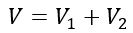
If the total voltage across the capacitor is V and the voltages across two dielectric regions are V1 and V2 respectively, then the total voltage (V) across the capacitor is the sum of the voltages across the individual dielectric regions:
Step 5: Capacitance Calculation
We substitute the electric field values to reach the final capacitance formula:
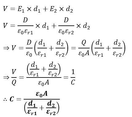
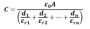
For a capacitor with n-composite dielectric mediums, we get,
Working Principle of Parallel Plate Capacitor
When a DC voltage source is connected across the capacitor plates, electrons accumulate on one plate while leaving the other plate deficient in electrons. As a result, equal and opposite charges develop on the plates.
An electric field is established between the plates through the dielectric medium. The dielectric prevents direct current flow while allowing energy to be stored in the electric field.
The stored energy is given by:
where:
- W = Energy stored (J)
- C = Capacitance (F)
- V = Applied voltage (V)
Types of Parallel Plate Capacitors
Parallel plate capacitors can be classified based on the dielectric medium used. The following are some common types of parallel plate capacitors.
- Air Capacitor – In this type of capacitor, air or vacuum is used as the dielectric medium between the plates of the capacitor to store electrostatic charge.
- Mica Capacitor – In this type of capacitor, mica is used as the dielectric medium. The use of mica as a dielectric medium increases its capacitance.
- Ceramic Capacitor – It has ceramic as the dielectric medium to store electric charge.
- Paper Capacitor – It has wax paper as the dielectric medium between the metal plates of the capacitor.
Advantages of Parallel Plate Capacitors
The following are some major advantages of a parallel plate capacitor over other types of capacitors:
- Easy to design and manufacture.
- Compact in size, making them versatile.
- Have very low inductance because of the compact design.
- Provide faster response time.
- Very low internal resistance, making them energy efficient.
Disadvantages
The following are some key disadvantages.
- For the same capacitance values, these capacitors have larger sizes and higher weights as compared to other types of capacitors.
- Due to expensive dielectric materials, these capacitors are more expensive.
- Extreme environmental conditions like high temperature, humidity, etc. can greatly influence the operation and performance of the capacitors.
- They have limited voltage ratings and frequency responses.
- They have a capacitance tolerance range.
Applications of Parallel Plate Capacitors
Parallel plate capacitors are widely used in the following applications:
- Used in various electronic devices like, filters, UPS, oscillators, etc.
- Applications in power electronic circuits like inverters, choppers, motor drives, etc.
- Used in various communication devices like radio transmitters, receivers, wireless antennas, etc.
- Used for smoothing voltage fluctuations in power supplies.
- They are used in tuning circuits to adjust resonance frequency.
- Also used in various sensors like position sensors, pressure sensors, proximity sensors, etc.
- They provide protection against electrostatic discharge (ESD).
Solved Numerical Examples
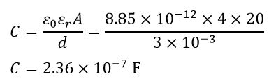
Example 1: Calculate the capacitance of a parallel plate capacitor having two plates of area 20 m2 and separated by a dielectric of 3 mm thick and of relative permittivity 4.
Solution:
Given data,
Area of plates, A = 20 m2
Distance between the plates,
d = 3 mm = 3 × 10⁻³ m
The Relative permittivity of the dielectric,
εr = 4
The capacitance of the given capacitor will be,
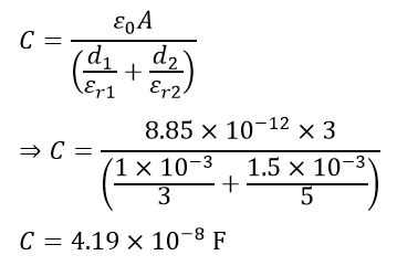
Example 2: A parallel plate capacitor has two metal plates of area 3 m2 and separated by two layers of different dielectric mediums. The relative permittivity of these layers are 3 and 5, respectively, and their thicknesses are 1 mm and 1.5 mm. Calculate the capacitance of the capacitor.
Solution:
Give data,
Area of plates, A = 3 m2
Thicknesses of dielectrics,
d1 = 1 mm
= 1 × 10⁻³ m;
d2 = 1.5 mm
= 1.5 × 10⁻³ m
Relative permittivity,
εr1 = 3 and
εr2 = 5
The capacitance of the capacitor will be,
Conclusion
The parallel plate capacitor is a fundamental building block in electrical engineering, essential for everything from basic signal filtering to sophisticated sensor technology. Successful design relies on balancing key factors: plate surface area, separation distance, and the properties of the dielectric material used.
As shown in our derivation, moving from a simple air-gap setup to a composite dielectric medium offers much finer control over capacitance, which is critical for high-performance systems. Whether you are performing standard calculations or modeling multi-layered insulation, these mathematical principles are the bedrock of reliable design.
Ultimately, balancing factors like physical size, material costs, and frequency response is the key to selecting and implementing the right capacitor for any electronic circuit.
Frequently Asked Questions
A dielectric material increases the capacitance by reducing the electric field intensity between the plates for a given charge, allowing for higher energy density.
For composite dielectrics, you calculate the equivalent capacitance by considering the layers as capacitors in series. The formula is C = A / Σ (dᵢ / ε₀ εᵣᵢ)
Because the capacitance is highly sensitive to changes in the distance (d) between plates or the dielectric properties, making it ideal for measuring pressure, displacement, and humidity.
Increasing the distance between the plates decreases the capacitance because capacitance is inversely proportional to plate separation.
The capacitance of a parallel plate capacitor is calculated using the formula C = (ε₀ εᵣ A)/d, where A is the plate area, d is the distance between the plates, ε₀ is the permittivity of free space, and εᵣ is the relative permittivity of the dielectric material.
Read Next: