A variable resistor is a type of resistor whose resistance can be adjusted according to the requirement. It permits the change in the current or voltage in an electric circuit as per Ohm’s law.
The term ‘variable’ means ‘changing.’ Thus, the resistance of a variable resistor can be varied as per the requirements of the circuit. Variable resistors are important components for various electronic devices like volume controllers, voltage regulators, and calibration devices. Unlike fixed resistors, these components provide the dynamic control necessary for tuning and biasing sensitive circuits.
In this article, we will discuss variable resistors and will cover their various concepts, such as definition, working principle, circuit symbols, formula of resistance, and applications.
What is a Variable Resistor?
A variable resistor is a passive circuit element used in electrical and electronic circuits and devices to insert a resistance that can be changed as per requirements. It is simply a resistor with an adjustable resistance mechanism. By adjusting its resistance, it regulates the electric current in the circuit by changing the effective length of the resistive track via a movable wiper contact.
A three-terminal variable resistor (two fixed ends and a movable wiper) used as a potential divider is called a potentiometer. In this configuration, all three terminals are utilized: the two fixed ends are connected to the voltage source, while the wiper provides a variable output voltage proporti onal to its position
If two terminals of the potentiometer are used to get the variable resistance, it is called a rheostat. A rheostat primarily controls the current flow in a circuit by using only one fixed terminal and the wiper; as the wiper moves along the track, the resistance between these two points varies. The resistance can be adjusted mechanically or electronically.
The potentiometer whose resistance can be changed electronically is called a digital potentiometer.
Variable Resistor Symbol
The circuit symbol of a variable resistor is shown in the following figure.
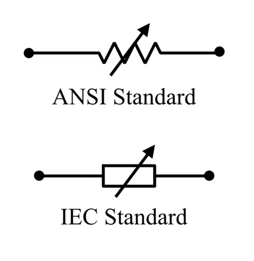
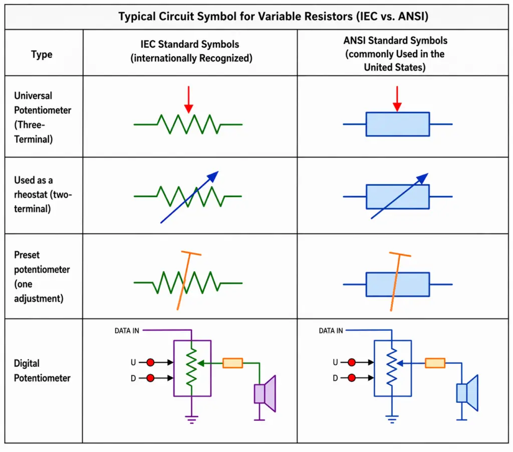
The following diagrams illustrate commonly used variable resistor symbols defined by IEC (International Electrotechnical Commission) and ANSI (American National Standards Institute) standards.
Working Principle of a Variable Resistor
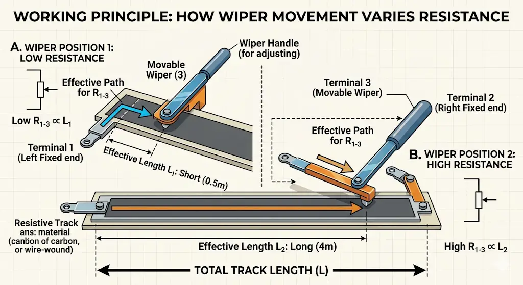
We get variation in the resistance by changing the effective length. This means the resistance of a variable resistor is changed by varying its length by some means.
A variable resistor typically consists of a long resistive element and a movable contact terminal called a wiper. The wiper can be moved along the length of the resistive element to adjust its effective length to change its resistance. As the wiper moves further from the fixed terminal, the resistive path length increases, thereby increasing the total resistance according to the formula R =ρ (l/A)
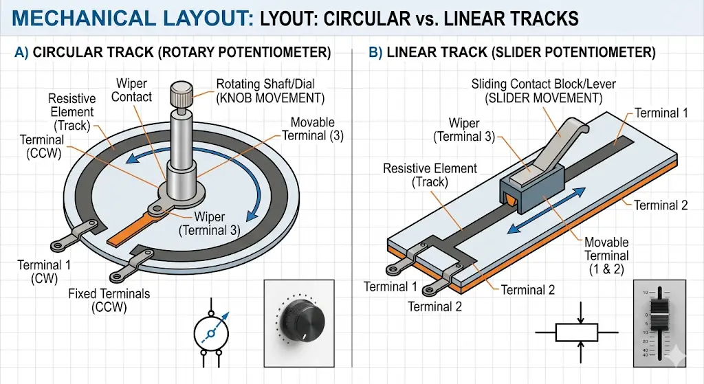
Track Geometry: Circular vs. Linear Tracks
The physical configuration of the resistive track determines the movement of the wiper and the overall form factor of the component:
- Circular Tracks (Rotary): These feature an arc-shaped resistive track where a knob or dial rotates the wiper along the arc. These are common in volume knobs and panel-mounted controls.
- Linear Tracks (Slider): In this design, the resistive track is a straight line. The wiper is moved by a slider or lever traveling horizontally along the track. These are widely used in audio mixing consoles.
Resistive Element Materials
The material used for this resistive element determines the component’s performance and suitability for different environments:
- Carbon Composition: Ideal for general-purpose high-resistance applications where precision is less critical.
- Wire-Wound: Used for high-power applications where heat dissipation is critical, such as in motor control. These consist of a metal wire wrapped around an insulating core.
- Cermet (Ceramic-Metal): Offers high stability and precision, commonly found in trimpots and circuits requiring low temperature coefficients.
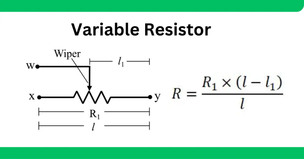
How to Calculate Resistance of Variable Resistor?
The value of the resistance depends on the position of the wiper on the resistive element.
We can use the following formula to compute the resistance of a variable resistor for a given wiper position on the element:
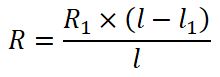
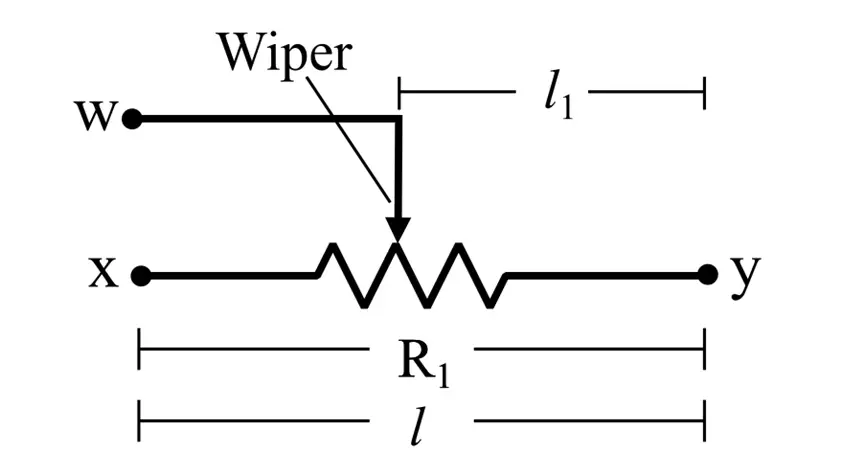
Where R is the resistance of the variable resistor in ohms for a given wiper position, R1 is the resistance of the element between ‘x’ and ‘y’, l is the total length of the element, and l1 is the distance between the wiper and end ‘y’ of the element.
For example, if a variable resistor has 100 Ω between ends ‘x’ and ‘y’. The total length of the element is 10 m. If the wiper is placed 4m from point ‘y’. Then, calculate the effective resistance.
Here, R1 = 100 Ω, l = 10 m, l1 = 4 m. Then,the resistance between the wiper and terminal ‘x’
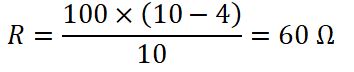
The resistance between the wiper and terminal ‘y’ is: 100-60= 40 Ω
Understanding Resistance Taper: Linear vs. Logarithmic(Audio)
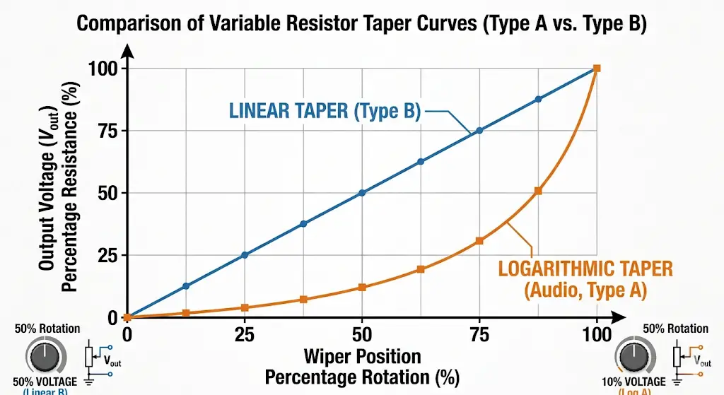
The relationship between the mechanical position of the wiper and the electrical resistance produced is known as the “Taper.” Choosing the correct taper is vital for the specific application of the circuit.
1. Linear Taper (Type B)
In a linear track, the resistance is directly proportional to the wiper’s displacement. If you move the wiper exactly 50% across the track, the resistance will be exactly 50% of the total value. For example, in a 100 kΩ linear potentiometer, setting the knob at the 50% midpoint results in exactly 50 kΩ.
- Identification: These are typically marked with a “B” prefix (e.g., B10K for a 10 kΩ linear pot).
- Best For: Precision measurement, voltage division, and lighting dimmers where a uniform change is desired.
2. Logarithmic Taper (Type A)
Also referred to as an “Audio Taper,” these tracks do not change at a constant rate. Instead, the resistance follows an exponential curve. For a 10 kΩ logarithmic resistor, the midpoint (50% rotation) might only provide 1 kΩ of the total resistance.
- Identification: These are typically marked with an “A” prefix (e.g., A10K).
- Best For: Volume controls in audio equipment. Because human hearing perceives sound intensity on a logarithmic scale (decibels), a logarithmic taper makes the volume increase feel “smooth” and natural to our ears. If a linear resistor were used for volume, most of the sound change would happen in the first 10% of the turn.
Types of Variable Resistor
Variable resistors, also known as adjustable resistors or potentiometers, come in several types, each suited for different applications. Here are the main types: It functions as a resistive divider and is typically used to generate a voltage signal depending on the position of the potentiometer.
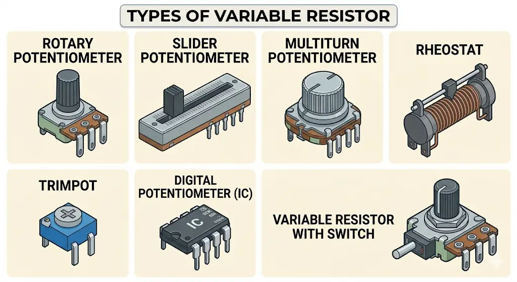
Potentiometer
A three-terminal resistor with a sliding or rotating contact forms an adjustable voltage divider. The potentiometer is the most commonly used variable resistor. It functions as a resistive divider and serves as a voltage divider. and is commonly utilized to produce a voltage output based on the potentiometer’s position; typical applications are volume controls in audio equipment, tuning circuits, and adjustable power supplies.
Rheostat
A two-terminal potentiometer is used as a variable resistor to adjust current. It is used in light dimmers, motor speed control, and heater controls. Unlike potentiometers, rheostats must carry the full circuit current, so they are often built with heavy-duty wire-wound elements.
Trimpot (Trimmer Potentiometer)
A small potentiometer typically used for fine-tuning and calibration in circuits. It is often adjusted with a small screwdriver. Common applications include instrument calibration, setting bias in amplifiers, and adjusting sensor sensitivity. These are often considered “preset” resistors because they are not intended for frequent adjustment by the end-user.
Digital Potentiometer (Digital Pot)
A digital potentiometer is a type of potentiometer that is controlled electronically rather than mechanically and is typically used in digital circuits. Common applications include Digital volume controls, automatic gain control, and programmable filters.
Specialized Types
- Slider Potentiometer: A sliding potentiometer is adjusted by sliding contact along a track rather than rotating a knob. It is often used in audio mixing consoles, equalizers, and other audio equipment.
- Multiturn Potentiometer: A potentiometer that provides precise control through multiple turns of the adjustment knob to cover the entire resistance range. Ideal for precision tuning applications, such as in lab instruments and measurement devices.
- Variable Resistor with Switch: A variable resistor that incorporates a switch to turn the circuit on or off. It is used in devices where both variable resistance and an on/off switch are required, such as in some power tools and appliances.
Advantages of Variable Resistor
The following are some important advantages.
- They provide flexibility in the circuit, as they have variable resistance that can be changed as needed.
- It provides precise and continuously adjustable resistance in the circuit.
- They can be fixed easily into an electronic circuit.
- They provide a cost-effective solution for adjustable resistance in a circuit.
- It is a highly versatile component, as it can be used in various types of electronic circuits and devices.
- They allow for easy recalibration of aging circuits without the need to desolder and replace components.
Applications of Variable Resistors
The following are some key applications.
- Current Control: Used in electronic circuits to control the strength of the electric current. They act as a potentiometer and control the output voltage across the audio device. Logarithmic-type resistors are better than linear ones because they exactly match the human perception of loudness, preventing sudden jumps in volume.
- Speed Control: Used in fan regulators for speed control purposes. By varying the resistance in series with the motor, the voltage drop is adjusted to modulate rotational speed.
- Lighting: They are also used in light dimmer switches to control the intensity of light produced by the lamps. This is achieved by using the variable resistor to control the gate of a TRIAC or by direct current limitation.
- Power Regulation: Applications in power supplies to regulate their output voltage and currents. They are often used as feedback components in voltage regulator circuits to set the desired output level.
- Audio Systems: Used in audio devices and systems to control the volume, bass, and tone of the output sound. The use of an “Audio Taper” ensures that the adjustment feels natural to the human ear.
- Instrument Calibration: Applications in various types of calibration devices and sensors for fine calibration of different types of instruments. Trimmer potentiometers (Trimpots) are the standard choice here for “set-and-forget” internal adjustments.
- Television: Used for adjusting the color, brightness, contrast, and position of the picture on a television screen. Linear variable resistors are typically preferred here to ensure the adjustment is predictable and uniform across the display.
- Motion Control: They are used to control the speed, torque, and direction of motors, servos, fans, pumps, etc. In these industrial applications, wire-wound variable resistors are the standard choice due to their superior heat dissipation capabilities and ability to handle high-wattage loads without failure.
- Transducers and Sensors: Variable resistors like thermistors (temperature-sensitive) and LDRs (light-sensitive) act as transducers, converting physical environmental changes into measurable electrical signals for automation and monitoring.
- Analog Computing and Computation: Variable resistors perform mathematical and logical operations within analog computers and calculators. When used as potentiometers, they calibrate the input or output voltages across operational amplifiers or comparators. For instance, summing amplifiers process multiple voltages using variable resistors as scaling weights, while subtractors utilize them to invert and balance input signals. These components allow analog systems to solve complex equations and process signals in real-time without requiring a digital processor.
Conclusion
In conclusion, in this article, we have described all the major concepts of variable resistors, including definition, working principle, formula, and applications. This resistor is a crucial circuit element used in various electronic circuits and devices to adjust the amount of voltage and current and its application increases the flexibility in circuit design by providing an easily adjustable resistance.
By selecting the correct material—whether carbon, cermet, or wire-wound—and choosing between linear and logarithmic tapers, engineers can ensure their circuits perform reliably under varying conditions.
Read Next: