A shunt resistor is a passive electronic circuit element commonly used to detect current flow. Thus, it acts as a current-sensing resistor. The detection of electric current flow in electrical and electronic applications is a crucial thing.
This article describes the shunt resistor, its definition, working, calculation of resistance, and applications.
Definition of Shunt Resistor
A shunt resistor is a passive electronic circuit component having a very low resistance value to provide a path for electric current in an electric circuit.
Shunt resistors are generally manufactured with a material having a low-temperature coefficient of resistance.
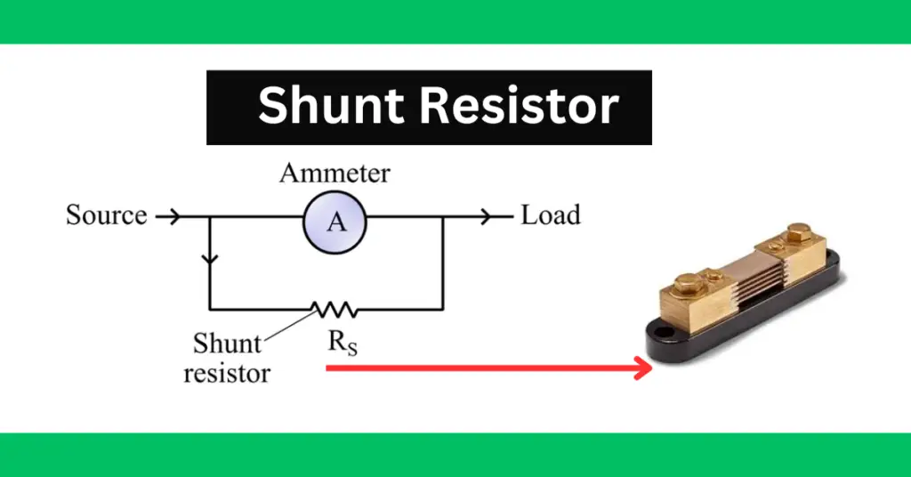
One most common application of electric shunt is seen in ammeters to measure electric current in a circuit. It is also used to convert a galvanometer into an ammeter.
When a shunt resistor is connected to an ammeter, it increases the range of the ammeter to measure more amount of current with the same instrument.
Another important point to note about the electric shunt is that it is also connected in series with the load through which the current is to be measured.
Function of Shunt Resistor
The term “shunt” means to “divert” or “divide”. Thus, the primary function of a shunt resistor is to divert an electric current flowing in a circuit.
When the shunt resistor is connected in parallel with the ammeter, it provides a low resistance path to divert the electric current from the main circuit. The following figure shows the electric shunt circuit, which is also called a current divider circuit.
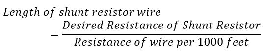
How to Construct a Shunt Resistor?
The shunt resistor is usually designed by using a fine wire of copper. The size or length of the resistor is estimated depending on the value resistance desired in the circuit. The value of shunt resistance determines the range extension of the ammeter.
We can use the following formula to compute the length of the shunt resistor wire:
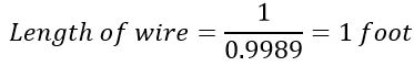
For example, if we use a copper wire of 10 AWG and the desired shunt resistance is 1 mΩ, then the length of the copper wire will be,
Working of Shunt Resistor
The electric shunt provides a path of low resistance for the flow of electric current. As we mentioned above that the shunt resistor is connected in parallel with the ammeter and allows a portion of the total circuit current to flow through it.
This resistance measures the electric current passing through it as per ohm’s law, i.e.

Where R is the value of the electric shunt and V is the voltage across the shunt.
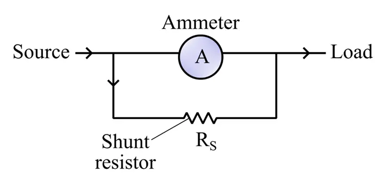
Extending Range of Ammeter using Shunt Resistor
Let us consider, we have an ammeter having an internal resistance of Ra ohms and it can measure only a small current Ia.
Now, to increase the range of this ammeter, we connect a resistor Rs in parallel with the ammeter coil of resistance Ra. The circuit diagram of this arrangement is shown in the following figure.
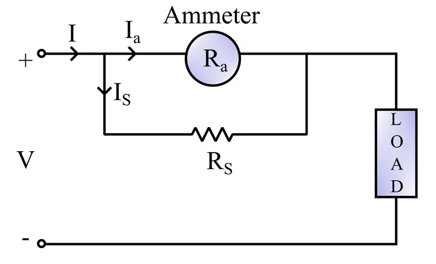
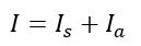
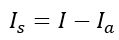
In this circuit, if I is the total current drawn from the source. It divides into two parts namely, Ia and Is. Thus, as per the KCL, we have,
Here, the current IS is flowing through the shunt resistance and Ia is the portion of the total current flowing through the ammeter coil.
Rearranging the above equation to obtain the current through the resistor, we get,
Since the resistors Ra and RS are connected in parallel, hence the voltage across them is the same, i.e.
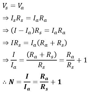
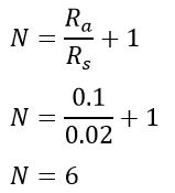
Here, N is called the multiplying power of the shunt resistance. It is a ratio of the total current and the full-scale deflection current.
Example of Multiplying Power
The resistance of the shunt resistance is 0.02 ohms and the galvanometer resistance is is 0.1 ohms. Calculate the multiplying power of shunt resistance.
Given data-
Rs=0.02 Ω
Ra = 0.1 Ω
multiplying power is,
Sizing of Shunt Resistor
The sizing of the resistor depends on the amount of voltage drop required across he resistance at the desired current.
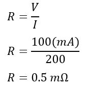
For example, if you require 100 mV across the resistor when current flows through it is 200 amperes. The value of resistance, in this case, will be;
Advantages
The following are some key advantages of shunt resistors.
- It provides protection against over currents and overvoltages.
- It is very easy and simple to construct.
- They can be employed in both AC and DC circuits.
- Also provides immunity against electromagnetic noise.
Applications
Some important applications are listed as follows:
- Used to extend the range of an ammeter.
- Also used to convert a galvanometer into an ammeter.
- Used in electronic circuits to reduce or prevent high-frequency noise issues.
- Used in overload protection systems.
Specifications of a Shunt Resistor
Resistance Value
Shunt resistors typically have resistance values in the milliohm (mΩ) or microohm (μΩ) range. The value of resistance depends on the voltage and current requirement for a specific application.
Tolerance
The resistor’s tolerance indicates the allowable variation in resistance value from the specified value. The typical tolerance value of shunt resistors are ±1%, ±2%, ±5%, etc.
Maximum Current Rating
Many parameters are paramount for the selection of a shunt resistor. One of the important parameters is the maximum current rating. The maximum current rating is the maximum current that can safely flow through the resistor. If more than the rated current flows through the resistor, the excessive heat (IR) in t
Voltage Drop
The maximum current rating of the resistor is given with a voltage drop across the resistor. For example, 100 mV @ 200 A shunt resistor has a 100 mV drop across it when 200 amperes current flow through it. The resistance of the shunt will be, in this case, is R= 100/200=0.5 mΩ.
The shunt resistances are available in 50,75 and 100 mV at the maximum current rating.
Power Rating
It is the maximum amount of electric power that the resistor can sustain at a specified ambient temperature. The resistor will function properly if the amount of power dissipation remains within its specified power parameter. If it exceeds, it can cause damage to the resistor or cause a change in the resistance value.
Temperature Coefficient of Resistance
The resistance of the conductor increases with an increase in the operating temperature. Therefore, resistance has a positive temperature coefficient. The temperature coefficient of resistance specifies the change in resistance value with a change in temperature by per degree Celsius. TCR is usually expressed in parts per million per degree Celsius (ppm/°C).
Derating Factor
Shunt resistors generally have a derating factor of 66 percent for continuous operation for a run time of more than 2 minutes. If shunt resistors operate at higher temperatures, the increased temperature negatively affects the measurement accuracy. The drifts in the measurement occur if shunt resistance operates above 80 °C. and resistance gets permanently damaged above 140 °C.