In this article, we will discuss different types of DC motors, their definitions, applications, and characteristics equations.
An electric motor is an electromechanical energy conversion device that converts electrical energy into mechanical energy. Therefore, the input of an electric motor is electricity, while the output is mechanical energy in the form of the shaft’s rotation.
Depending on the type of electricity input, electric motors are classified into two major types, namely,
- DC Motor or Direct Current Motor
- AC Motor or Alternating Current Motor
An AC motor operates using alternating current, whereas a DC motor requires direct current. However, in this article, we will only consider DC motors.
What is DC Motor?
An electrical machine that converts direct current electricity into mechanical energy in the form of rotation of the shaft is called a DC motor. A typical DC motor consists of two main parts: the field system and the armature. The armature is the one that produces the required operating torque to drive the mechanical load, while the field system produces the working magnetic flux in the motor.
Types of DC Motors
Depending on the method of excitation used, the DC motors are classified into two types, viz.
- Separately Excited DC Motor
- Self-Excited DC Motor
Separately Excited DC Motor
A type of DC motor in which the required excitation to the field winding is provided using an external supply is known as a separately excited DC motor.
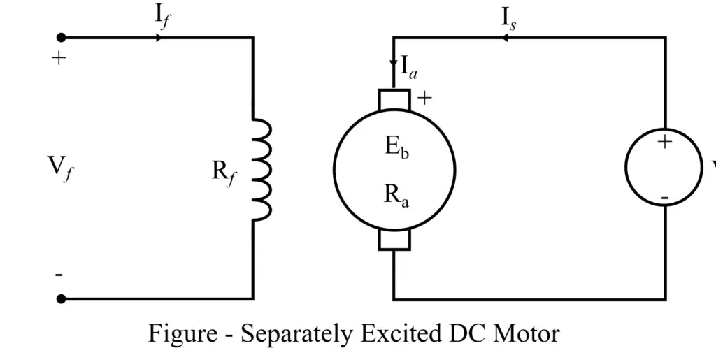
A circuit diagram of a typical separately excited DC motor is shown in the figure. It consists of an armature that carries the armature winding that is directly supplied from the DC mains. The field winding of the motor is supplied by a DC battery to produce the required working flux in the motor.
The separately excited motors are rarely used in practice due to some technical and economic reasons. From the circuit diagram of the motor, we may write the following important expression representing the different electrical characteristics of the motor.
(1). Armature current of the motor:

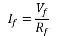
(2). Field current of the motor:
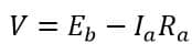
(3). Supply voltage given to the motor:
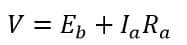
Where Eb is the back emf, and Ra is the armature resistance.
Self-Excited DC Motor
The self-excited DC motor is the one in which the current required to excite the field winding is supplied by the motor itself. Therefore, these motors are very popular over separately excited DC motors in practical applications.
Depending on the connection of the field winding of the motor with the armature winding, the self-excited DC motors are further classified into three main types:
- DC Serie Motor
- DC Shunt Motor
- Compound Wound DC Motor
DC Series Motor
The series DC motor is the one in which the field winding is connected in series with the armature winding, as shown in the figure.
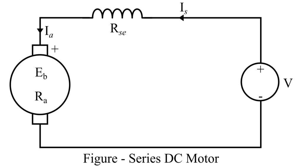
From the above circuit, it is clear that the series field winding of the motor carries the entire armature current; therefore, it is designed to have low resistance. In practice, the series field winding is made of fewer turns of thick wire.
By referring to the circuit diagram, the important characteristic equations of a series DC Motor can be written as,
(1). Armature current of series DC motor:

(2). Voltage equation of the DC series motor:
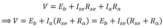
In the case of DC series motors, the change in the supply current causes a change in the magnetic field, which in turn causes variation in the speed of the motor. Therefore, series DC motors are variable-speed DC motors.
One of the most important characteristics of a DC series motor is that it produces very high torque at low speeds and vice-versa. It is always taken into care while using a series DC motor that it attains a dangerously high speed at no load or light load.
Hence, series DC motors are used in applications where high starting torque is required, such as electric traction, cranes, lifts, elevators, sewing machines, air compressors, etc.
DC Shunt Motor
A shunt DC motor is a type of DC motor in which the armature winding and field winding are connected in parallel. The circuit diagram of a shunt DC motor is shown in the following figure.
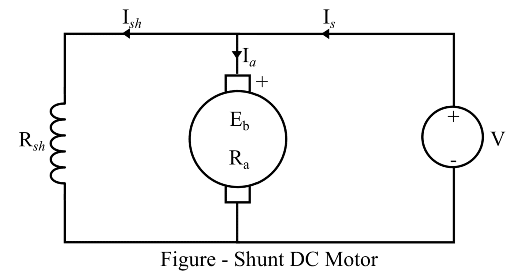
In the case of the shunt DC motor, the field winding is designed to have high resistance. For that, it is made with a large number of turns of thin wire. So that it carries only a small fraction of the total supply current, the rest of the current flows through the armature winding to produce the working torque.
We can write the following characteristics equations for the shunt DC motor by referring to its circuit diagram.
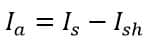
(1). Armature current of the shunt DC motor:
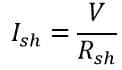
(2). The field current in the shunt winding:
(3). Voltage equation of the shunt DC motor:
Shunt motors are considered constant-speed DC motors. Hence, they are used in applications such as lathes, drill machines, spinning machines, weaving machines, etc.
Read detailed article on: DC Shunt Motor : Construction, Speed Control & Characteristics
Compound DC Motor
As its name implies, the compound DC motor is the compound (combination) of both series and shunt DC motors. A type of DC motor that consists of both series field winding and shunt field winding to produce the required magnetic flux in the machine is called a compound DC motor.
Depending on the series and shunt field winding arrangement in the motor circuit, the compound DC motors are further classified into the following two types.
- Short-Shunt Compound DC Motor
- Long-Shunt Compound DC Motor
Short Shunt Compound DC Motor
The type of compound DC motor in which the parallel combination of shunt field winding and the armature winding is connected in series with the series field winding is known as a short-shunt compound DC motor.
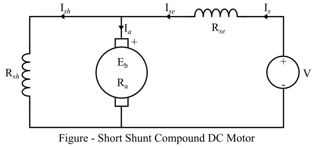
The circuit diagram of the short-shunt compound DC motor is shown in the figure. From this circuit diagram, we can write the following expressions describing the motor characteristics:
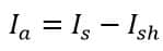
(1). Armature current of the short shunt DC motor:
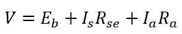
(2). Voltage equation of the short shunt DC motor:
Long Shunt Compound DC Motor
A compound wound DC motor in which the series combination of armature winding and the series field winding is connected in parallel with the shunt field winding is known as a long-shunt compound DC motor.
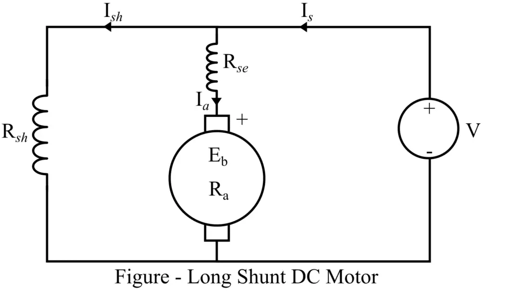
The circuit diagram of a long shunt compound DC motor is shown in the figure. By referring to this circuit, we can write the following characteristics equations of the long shunt DC motor:
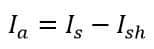
(1). Armature current of long shunt DC motor:
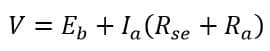
(2). Voltage equation of the long shunt motor:
DC compound motors have a high starting torque (series field) and a finite speed at no load or light load (shunt field). Hence, they are extensively used in cutting tools, rolling mills, etc.
Both short-shunt and long-shunt compound DC motors are classified into two types, namely, cumulatively compound motors and differentially compound motors. In the cumulatively compound motor, the fluxes of both series and shunt field windings assist each other, while in the differentially compound motor, the fluxes of both series and shunt field windings oppose each other. For this reason, the performance of differentially compound DC motors is poor; hence, they are not suitable for practical applications.
Related Articles:
- Types of DC Generators – Series, Shunt and Compound
- Starting Torque Of DC Motor
- DC Shunt Motor : Construction, Speed Control & Characteristics
- Speed Regulation of DC Motor | Definition and Formula
- What is the disadvantage of large exciting current in a transformer?
- Motor Generator(M-G) Set
- Difference between Stepper Motor and DC Motor
- Difference Between Servo Motor and DC Motor
- Why DC Series Motor should not be Started at No Load
- Difference Between DC Series Motor and Universal Motor
- Armature of DC Motor: Definition, Function, Parts & Working